- The Inner cylindrical face of the wheel arch is fixed. Use the View Cube to orient the part so that you have a clear view of the bottom face. Right-click on
Constraints under
Subcase 1 and select
New.
 All the entities that you will be creating will also appear in Model Entity list. This list will expand as the modeling progresses. The Model Entity list provides a means of easily applying entities to other subcases as well.
- When the
Constraint dialog appears, select the inner cylindrical face.
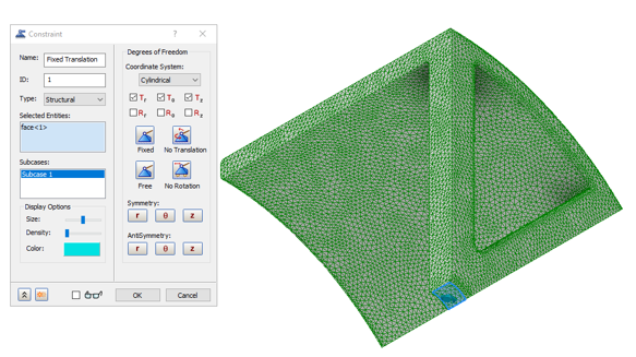
- Type
Fixed Constraint
for the
Name of the constraint. Change the Coordinate system to
Cylindrical and Uncheck the
Rr, R
θ
, and Rz boxes.
Note: In the Display Options section of the Constraint dialog, you can adjust the size, number, and color of the constraint symbols that appear in the part display.
- Be sure that Subcase 1 is selected in the Subcases list, and then click OK. This will automatically add the constraint to Subcase 1.
- Right-click on
Loads under
Subcase 1 and choose
New. In this subcase, the load is a 50 psi pressure applied to the outer surface of the wheel in the direction normal to the surface.
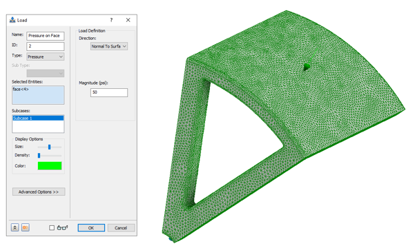
- Set Pressure as the Load type from the type drop-down.
- Enter Pressure on Face in the Name field.
- Select the Outer surface of the wheel and type in
50 psi.
Note: In the Display Options section of the Load dialog, you can adjust the size, number, and colour of the load symbols that appear in the part display
- Be sure that Subcase 1 below the Subcases list is selected.
- Then click OK.
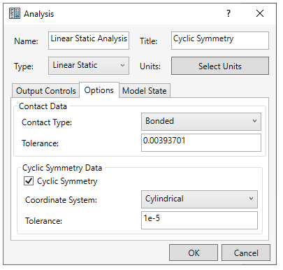
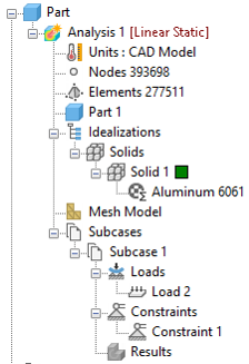
- In the tree view, right-click on Analysis 1 and select Edit.
- Type Linear Static Analysis for Name, type Cyclic Symmetry for Title, and select Linear Static for the analysis Type.
- Ensure that Displacement is checked under Nodal Output Control and Stress is checked under Elemental Output Sets.
- Switch to the
Options tab. Check the box under
Cyclic Symmetry, and set the Coordinate system to
Cylindrical. Make sure that the coordinate system selected inside the Options tab is the same selected while applying constraint, then click
OK.