Configure the inspection simulators.
In PowerInspect, the Simulate Program tab enables you to simulate the inspection sequence so that you can check the probe path for problems before running it on a CNC/DCC-controlled measuring device. When you create inspections for dual-column CNC machines, the tab contains a separate simulator for each column. Use the Dual Simulator Configuration dialog to specify which simulator is to be used to check each machine column.
- Click
.
The Dual Simulator Configuration dialog is displayed.
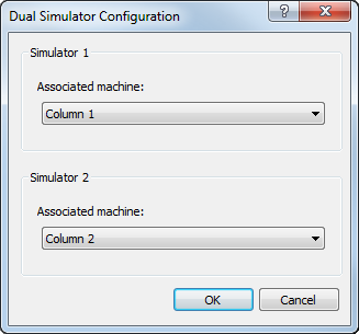
- In the Associated machine list for Simulator 1, select the name of the column you want to display as Simulator 1.
- In the Associated machine list for Simulator 2, select the name of the column you want to display as Simulator 2.
- Click OK to save your changes and close the dialog.
- Click to connect both columns to the measuring device.
- Select the Machine tab.
- In the Machine list, select Column 1.
- Use the Probe head, Probe tool, and Probe head angles areas to specify the probe assemblies for the column.
- If the names you have given to the assemblies do not match the tool definitions in the I++ Server, click
 to map the simulation tools to the I++ tools.
- In the Machine list, select Column 2 and repeat steps 8 to 10 for the second column.