Use the CAD tab to load, manage, and delete CAD models, and to view the details of model files.
To add a CAD model to the inspection document, click
 or press the
Insert key, then select the CAD file using the
Open dialog.
or press the
Insert key, then select the CAD file using the
Open dialog.
Alternatively, locate the model file in Windows Explorer, left-click and hold the file to select it, drag it into the main graphics window, then release the mouse button. To open multiple models, press and hold the Ctrl key while selecting the files.
To centre the CAD model on the table of the simulated measuring device, select Tools tab > Simulator panel > Auto Position, or right-click the PCS (CAD Datum) and select Auto Position from the context menu.
To remove a CAD model from the inspection document, select the CAD file, then click
 or press the
Delete
key.
or press the
Delete
key.
To reset user levels, click
 to return the CAD surfaces currently stored in
user-defined levels to their original levels.
to return the CAD surfaces currently stored in
user-defined levels to their original levels.
To change the orientation of a CAD model:
- Open the
Parts
 folder, select the CAD file, then click
 . The
CAD Details dialog is displayed. Alternatively, double-click the CAD file.
. The
CAD Details dialog is displayed. Alternatively, double-click the CAD file.
- Click the Transformation Matrix button.
- Use the Transformation Matrix dialog to rotate, translate, mirror and scale the model.
This enables you to position models independently so you can inspect an entire assembly. For example, when a part is symmetrical, the model may contain only one side of the part. In this case, you can import the model twice and mirror one of the models using a transformation.
To view detailed information for a CAD model, deselect
 . Select the button to view summary information for the model.
To highlight a CAD file, level, or object in the CAD view, click
 , then select the CAD file, level, or object entry.
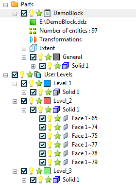
To display information about a CAD model, and its levels and objects, click
 next to
Parts
and
User Levels
next to
Parts
and
User Levels
 . For example:
To change the colour in which levels are displayed in the CAD view, click the coloured box
 next to the level. In the colour palette, click the colour you want to use for the level.
To hide a CAD level or object in the CAD view, click
 next to the entry. The icon changes to
 and the entry and any sub-entries are not displayed in the CAD view. Click the icon again to redisplay the entry.
To exclude a CAD level or object from an inspection, deselect the check box
 next to the entry. The entry and any sub-entries are excluded from the inspection. Select the check box
 to include the entry in the inspection again.
To exclude a CAD level or object from collision-checking, click
 next to the entry. The icon changes to
 and the icon of any parent entry changes to
 to indicate that one or more sub-entries are not included in the collision check. Click the icon again to include the entry in the collision check