The Offset alignment enables you to align a part by measuring a single specified position. The axes of the part must be aligned to the axes of the measuring device, so it is only suitable for use with Coordinate Measuring Machines (CMMs).
Note: Offset alignments are available only when creating inspections for CNC and Manual machines.
To create an Offset alignment:
- Select the Definition level in the inspection sequence.
- Click Alignments & Datums tab > Alignments panel > Offset. The Offset Alignment dialog is displayed.
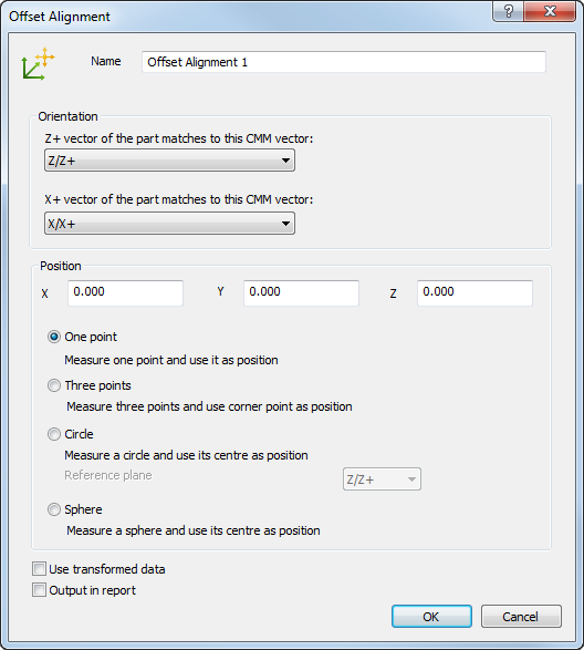
- Enter a Name for the alignment.
- In the Z+ vector of the part matches to this CMM vector list, select the axis of the Machine Datum that corresponds to the Z+ vector of the PCS (CAD Datum).
- In the X+ vector of the part matches to this CMM vector list, select the axis of the Machine Datum that corresponds to the X+ vector of the PCS (CAD Datum).
- In the X, Y, and Z boxes, enter the PCS coordinate of the point that corresponds to the measured point on the part.
- Choose a measurement method. Select:
- One point to probe the point that corresponds to the specified coordinates.
- Three points to specify the positions of the major planes by probing a point in the X, Y, and Z axes. The alignment point is calculated from the corner at which the planes meet.
- Circle to calculate the position of the point from the centre of a probed circle. Select an entry in the drop-down list to specify the reference plane on which the circle is located.
- Sphere to calculate the position of the point from the centre of a probed sphere.
- If the inspection sequence contains constructed features that use measurements taken by different measuring devices or from different device positions, select the Use transformed data check box. This converts the device coordinates to CAD coordinates so that all calculations use a common reference system.
The check box has no effect when all coordinates in the inspection are collected with one measuring device in one position, or when the inspection sequence contains no constructed features.
- To include the details of this item in the report, select the Output in report check box.
- Click OK to save the alignment and close the dialog.
Note: Before measuring the alignment, make sure the axes of the part are correctly aligned to the axes of the measuring device.