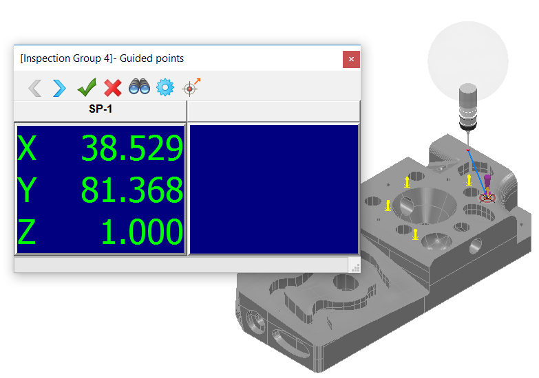
When you probe guided surface points, the CAD view displays the points as targets so you can probe them. For example:
When you are using a:
- fixed or touch trigger probe, PowerInspect accepts the point only when the probe is in the correct position on the part. The point is shown as a target in the CAD view and, if tracking is supported by your measuring device, the position of the probe is also shown. When the probe is in the centre of the target, take the point.
- rigid probe, you can trigger the probe continuously near the point. PowerInspect accepts the measurement when it is within the tolerance of the nominal position. For measuring devices that support sound, the pitch rises as the probe gets closer to the target.
Always orientate the axis of the probe towards the component when taking points using a rigid probe. Otherwise, PowerInspect may not offset the point correctly.
When you take the point, PowerInspect identifies the nearest location on the model and uses this to reset the position of the nominal. The updated nominal is then used to calculate the deviation of the measured point.
Using the Guided Points dialog
Use the Guided Points dialog to accept each point after probing. Click:
 to move to the previous guided point in the group, and to display its details on the left of the dialog. PowerInspect waits for you to probe the point.
 to move to the next guided point in the group. PowerInspect waits for you to probe the point.
 to save the probed points and close the dialog.
 to close the dialog and create the group without saving the probed points.
 to display the point to probe in a view perpendicular to the point's normal.
 to change the probing parameters.
 to position the probe at the target point. This button is available only for CNC connections.
The left of the dialog shows the position of the current guided point; the right of the dialog displays the difference between the position of the guided point and the probed point. The dL (deviation length) is the distance between the probed point and the guided point; the colour of the value indicates whether the probed point is within tolerance (green), below tolerance (light blue) or above tolerance (yellow).
The progress bar at the bottom of the Guided Points window shows how close the probe is to the point. When the bar is displayed in green, the probe is within tolerance.
