To specify the accuracy with which probed surface and edge points must match the CAD model:
- Click Measure tab > Current panel > Parameters.
- In the Measure Parameters dialog, select the Inspection Point tab.
- Enter the
Surface point defaults:
- Proximity criteria — Specifies the maximum distance that a measured surface point can be from the CAD surface. If the point exceeds this distance, it is not recorded.
- Maximum distance for guided points — Specifies the position tolerance for guided points. If the probed point exceeds this distance from the guided point, it is not recorded.
- Maximum distance to cutting plane — Specifies the maximum distance from probed points to the cutting plane of a section group. If a point exceeds this distance from the plane, it is not recorded.
Note: You cannot specify Maximum distance for guided points for OMV inspections. - Enter the
Edge points defaults:
- Proximity criteria — Specifies the maximum distance that a measured edge point can be from the CAD surface. If the point exceeds this distance, it is not recorded.
- Single point measurement — Select this check box to use one touch to create an edge point; the point is matched to the nearest edge to the touch point. Deselect this check box to use two touches to create each edge point: the first touch identifies the surface normal; the second touch identifies the position of edge point.
- Use pre-touch with rigid cylindrical probes — By default, PowerInspect measures edge points with a single touch for all types of probe. If you are using a rigid cylindrical probe and want to take a pre-touch point to identify the surface on which the edge is located, select this check box.
- Cylindrical probe active length — If you are using a cylindrical probe to measure edges, enter the length of the probe that can be used to probe the points.
Note: You cannot use Single point measurement or cylindrical probes on OMV inspections. - Enter the
Guided point calculation parameters:
- Tolerance for precise points — Specifies the maximum distance that a nominal can be from the CAD surface. If the nominal exceeds this distance, it is invalid.
- Research length — If you enter only two coordinates for a guided point, PowerInspect calculates the third coordinate by projecting the point along the remaining axis onto the CAD surface. Use this box to specify the maximum projection distance that PowerInspect can use.
Note: You cannot use Guided point calculation parameters on OMV inspections. - Enter the default
Waviness parameters:
- Calculate waviness — Waviness describes the widely spaced irregularities that can result from problems with the manufacturing process, for example, machine vibration. Select this check box to enable
PowerInspect to measure waviness as a percentage of the total points within surface inspection groups and point clouds: the higher the percentage, the smoother the surface.
The diagram shows how waviness is measured:
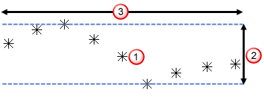
For each point
 ,
PowerInspect calculates the difference
,
PowerInspect calculates the difference
 between the highest and lowest points within the diameter specified by the
Width value
between the highest and lowest points within the diameter specified by the
Width value
 . It then reports the number of differences lying within the specified
Maximum value as a percentage of the total points.
. It then reports the number of differences lying within the specified
Maximum value as a percentage of the total points.
- Width — Specifies the comparison diameter.
- Maximum — Specifies the waviness tolerance.
When you increase the Width or calculate waviness for dense point clouds, PowerInspect takes longer to report the percentage.
- Calculate waviness — Waviness describes the widely spaced irregularities that can result from problems with the manufacturing process, for example, machine vibration. Select this check box to enable
PowerInspect to measure waviness as a percentage of the total points within surface inspection groups and point clouds: the higher the percentage, the smoother the surface.
- Select Save as default parameters if you want to use these values as the defaults for new inspections.