When the Stop on error check box is selected in the Simulate Program tab, simulations stop and display an error message if a potential problem is detected in the inspection. Use the Stop Simulation On dialog to specify the type of errors for which you want simulation to stop.
Note: The Simulate Program tab is available only when creating inspections for CNC and OMV machines.
To specify the error handling conditions for a simulation:
- In the
Simulate Program
tab, click the
Configure
button. The
Stop Simulation On dialog is displayed.
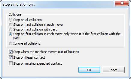
- Choose a
Collisions
option to specify how you want the simulation to handle any collisions that
PowerInspect detects. Select:
- Stop on all collisions to display an error message and suspend the simulation for every collision with the part.
- Stop on first collision in each move to display an error message and suspend the simulation when the first collision in a probe move occurs. Subsequent collisions in the move are ignored.
- Stop on first collision with part to display an error message and suspend the simulation each time the probe collides with the part boundary. If the probe continues to move through the part, subsequent collisions are ignored. If the probe leaves the part and collides with it again, the error message is displayed when the probe meets the boundary.
- Stop on first collision in each move only when it is the first collision with the part to display an error message and suspend the simulation when this is the first collision in a probe move and the first collision with the part. If the probe continues to move through the part, subsequent collisions are ignored. If the probe leaves the part and collides with it again, the error message is displayed when the probe meets the boundary. This is the default collision setting.
- Ignore all collisions to continue playing even when collisions are encountered. The Error handling list of the Simulate Program tab continues to displays all collisions, but no error messages are displayed.
- Specify any other type of errors you want
PowerInspect to detect. Select:
- Stop when the machine moves out-of-bounds to display an error when the probe moves outside its limits.
- Stop on illegal contact to display an error when a contact is detected near to start of measure move. The illegal contact zone is determined by the Head clearance and Probe assembly clearance settings in the Options dialog.
- Stop on missing expected contact to display an error when an expected contact is not detected. This check box has no effect when Ignore missing contact points is selected in the Options dialog.
- Click OK to save your changes.