When you display a model in a wireframe mode, the CAD view displays detail lines across each surface to provide an indication of the surface shape. Use the Change Meshing menu option to change the density of the detail lines for selected surfaces.
Note: To change the meshing for all surfaces in the model, use the Mesh settings in the Measure Parameters dialog.
To change the meshing for model surfaces:
- Select a wireframe option in View tab > Appearance panel.
- Select Home tab > Mouse Context panel > Surface Selector.
- In the CAD view, select the surfaces whose meshing you want to change.
- Right-click the CAD view and select Change Meshing from the context menu. The Meshing Parameters dialog is displayed.
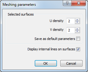
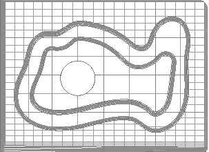
- By default, each patch formed by the laterals and longitudinals of a surface is divided into a 2x2 mesh. To change the size of the mesh for the selected surfaces, enter new values in the U density and V density boxes. Increase the values to show more lines are shown in the U and V parameter ranges. The following example shows a model with a U and V density of 2 for the inner surface, and a U and V density of 5 for the outer surface
- To use the current meshing values as the defaults for new models added to the document, select the Save as default parameters check box.
- To hide the detail lines for all surfaces and show only the laterals and longitudinals of the model, deselect the Display internal lines on surfaces check box.
- Click OK to close the dialog and save your changes.