When you select a  UserDefined probing method, PowerInspect activates the Probe Path Editor. The editor enables you to specify:
- the points to be measured on the part.
- intermediate points through which the probe must pass.
- probe movements between items in the inspection sequence.
The way you create points in the probe path differs depending on whether the UserDefined method is selected for a geometric feature or for an inspection group.
To create the probe path for a geometric item or surface inspection group:
- Create an inspection item. The Inspect dialog for the item is displayed in the Features tab.
- In the Inspect dialog, select a UserDefined probing method from the Probing method list. In the CAD view, the cursor changes to
 to indicate the Probe Path Editoris active.
 - To create the points in the probe path for a geometric item:
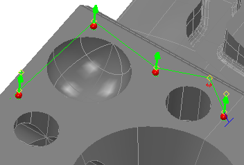
- To add a probe point, double-click the model. A red sphere is displayed at the probing position, and the approach point is shown as a yellow diamond.
- To add an intermediate point, press and hold the Shift key, then double-click the model. A yellow diamond is displayed at the intermediate position, and the normal distance from the model surface is shown as a green line terminated by a red diamond. Alternatively, right-click the CAD view, select Define First Point or Define Last Point from the context menu, and then enter the position in the Point Coordinates dialog.
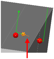
Intermediate points are non-contact positions on the probe path through which the probe must pass. Use them to prevent collisions with the part; to move the probe to a safe location before a head rotation; and to control probe movements between items in the inspection sequence. For example:
Collision:
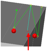
Intermediate point:
- To insert a probe point within the probe path, right-click the path, select Insert from the context menu, and then double-click the model.
- To insert an intermediate point within the probe path, right-click the path, select Insert from the context menu, press and hold the Shift key, then double-click the model. Alternatively, select Split Here from the context menu to insert an intermediate point midway between two points.
- To move a probe point, left-click and hold the red sphere, drag the point to its new position, and then release the mouse button. To restrict the move to one axis, press and hold the X, Y, or Z key before dragging the point.
- To move an intermediate point, left-click and hold the red diamond, drag the point to its new position, then release the mouse button. To restrict the move to one axis, press and hold the X, Y, or Z key before dragging the point. Alternatively, right-click the yellow diamond, select Move Point from the context menu, and then specify the exact coordinates for the position in the Point Coordinates dialog.
- To change the safe distance for an intermediate point, left-click and hold the yellow diamond, drag the diamond up or down, then release the mouse button.
- To use the current probe-tip position for an intermediate point, right-click the yellow diamond, and then select Move to CMM Position from the context menu.
- To delete a probe point, right-click the red sphere, and then select Delete from the context menu.
- To delete an intermediate point, right-click the yellow or red diamond, and then select Delete from the context menu.
To create the points in the probe path for a surface inspection group:
- To add a guided surface point, double-click the model. A red sphere is displayed at the probing position, and the approach point is shown as a yellow diamond.
- To add an intermediate point, move the cursor over the path or over the extensions from the first and last points in the path. When a grey diamond is displayed, click the diamond, drag the point to a position, then release the mouse button. The diamond is displayed in yellow. By default, the extension from the last specified point is highlighted in blue.
- To insert a guided surface point within the probe path, click the path, then double-click the model.
- To insert an intermediate point within the probe path, right-click the path, and then select Split from the context menu.
- To move a guided surface point, click the red sphere, drag the point to its new position, then release the mouse button. Alternatively, right-click the sphere, select Edit from the context menu, then enter the position in the Point Coordinates dialog.
- To move an intermediate point, click the yellow diamond, drag the point to its new position, then release the mouse button. Alternatively, right-click the diamond, select Edit from the context menu, then enter the position in the Point Coordinates dialog.
- To use the current probe-tip position for an intermediate point, right-click the yellow diamond, and then select Move to CMM Position from the context menu.
- To delete a guided surface point or intermediate point, click and hold, then drag the cursor to draw a rectangle over the points you want to delete. When the points are selected, release the mouse button, then right-click the CAD view and select Delete from the context menu.
- Complete the probe path, then click the OK
 button in the Inspect dialog to save the path and close the Probe Path Editor.
 button in the item's Inspect dialog, and then select a UserDefined method.