The by normalised units option in the Surface Parameters dialog enables you to use the model's surface parameterisation to control the density and location of probe points on a surface. It is similar to the by parametric units option except that the distances and limits are normalised to the range [0,1].
The boxes that control the stepover and pitch distances of the probe path depend on the u and v directions of the selected surface. Here, as in the parametric units example, the U box specifies the stepover distance between rows, and the V box specifies the pitch distance between points.
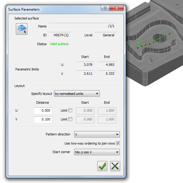
For example, only one row of probe points is displayed on the selected surface:
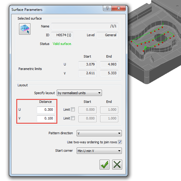
To produce three rows of probe points, you must reduce the values to scale. For example:
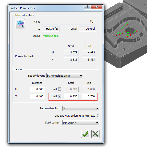
Similarly, if you want to restrict the probe path to only part of the surface, you must also scale the Limit values. For example: