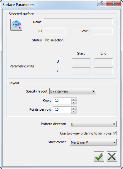
The SelectedSurface probing method enables you to generate a raster probing pattern for a specified surface. Use the Surface Parameters dialog to select the surface and to specify the parameters controlling the probe pattern.
To specify the surface and probing parameters:
- In the Features tab, select the SelectedSurface method, and click the Parameters
 button. The Surface Parameters dialog is displayed.
For example:
- Click the Select Graphically
 button.
The Select Surface dialog is displayed.
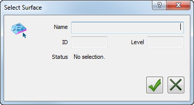
- On the CAD model, left-click the surface you want to inspect. The Name, ID, Level, and Status of the surface are displayed.
- Click the OK
 button to confirm the surface and close the dialog. The details and the parametric limits of the surface are displayed in the Surface Parameters dialog.
 - In the Specify layout list, choose the method to be used to create the probe path. Select:
- by parametric units to use the parametric units of the surface to specify the stepover between rows and the pitch between points.
- by normalised units to use the normalised parametric units of the surface to specify the stepover between rows and the pitch between points.
- by intervals to specify the maximum number of rows and the maximum number of probe points in each row.
- In the Pattern direction list, select the direction of each row in the probe path.
- Select the Use two-way ordering to join rows check box to alternate the direction of the probe path between rows. Deselect the check box to use the same direction for each row.
- In the Start corner list, select the position at which you want the probe path to start.
- Click the OK button to save your changes and generate the probe path.