To create a Solid Pocket feature:
- Create a solid.
- Click Solid tab > Feature panel > Pocket.
- Use the cursor to position the origin of the feature on the solid, or enter coordinates into the status bar.
- Use the options on the four tabs of the
Pocket dialog to create the Pocket feature. Each tab is described separately:
- Dimension tab
- Corners tab
- Fillets tab
- Plane Details tab
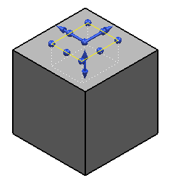
3D instrumentation is displayed on the feature. As an alternative to entering the information into the dialog, you can use the handles to define the length, width and height of the feature. You can also define the corner fillets using the handles in each corner of the feature. The value boxes on the dialog are updated to reflect the settings defined by the instrumentation.
- Click
Apply
to create the pocket. The pocket feature
 icon is added to the solid tree.
If the feature definition is invalid (for example if the fillet radius is too large), the Apply button is not selectable and the graphic show a dotted outline of the feature.
To edit a Pocket or Protrusion, double-click the feature icon in the solid tree, or the object in the graphics window, to display the relevant dialog. You can also use Ctrl+Click to simultaneously edit multiple pockets or protrusions.