The Plane Details tab lets you specify the workplane for the feature.

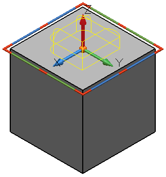
Position — The location of the workplane on the feature is defined using this panel.
The default workplane position is the centre of the feature.

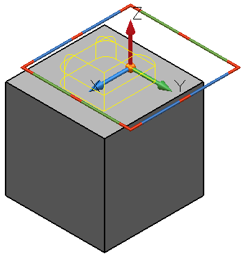
Selecting an alternative setting specifies the workplane accordingly. The example below specifies the workplane at the middle of the left edge of the pocket/protrusion.

Details — The workplane for the feature is defined using these options. The usual workplane instrumentation is displayed whilst this page of the form is selected.
Relationship — Specify the relative position of the pocket or protrusion with respect to the solid by selecting the Solid Feature Relationship  button.