This morphing method uses two points and enables you to make bulges in the model or apply simple bending or stretching distortions.
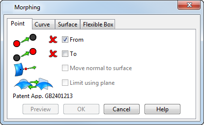
Use the Point tab of the Morphing dialog to select the two points and specify the morph.
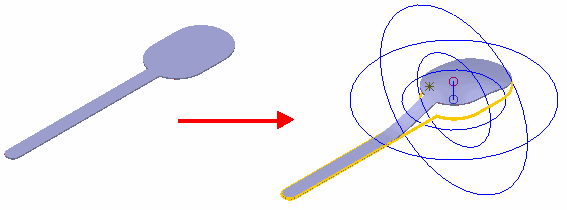
When you create the morph, the bulge produced by the distortion is centred on the origin point and the height and direction of the bulge is determined by the distance from the origin point to the distortion point.
To create the morph:
- Click the model or use the
Position dialog to select the
From
point for the morphing process. This is the origin point that usually lies on the surface of the model. It is shown as a small blue circle.
- In many cases, when you select the
From
point, a
To (distortion) point is automatically chosen, indicated by a small red circle, and an initial bulge displayed.
- If the selection you made for the
From
point does not automatically generate a bulge, the distortion point and the origin are in the same place.
- In many cases, when you select the
From
point, a
To (distortion) point is automatically chosen, indicated by a small red circle, and an initial bulge displayed.
- Select the To option and select or modify the distortion point that can lie anywhere in space, and is indicated by a small red circle.
- Modify the size and shape of the distortion by using one of the following methods:
- Drag the point to be modified.
- Use the Morphing or Position dialog to change the position of the From and To points.
- Use the two spheres to define the extent and shape of the bulge. You can change the bulge by using the mouse to drag a sphere. The graphics are updated when you release the mouse button.
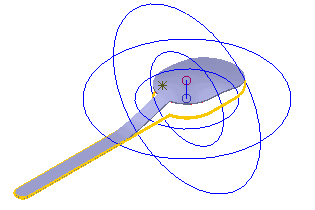
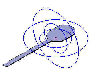
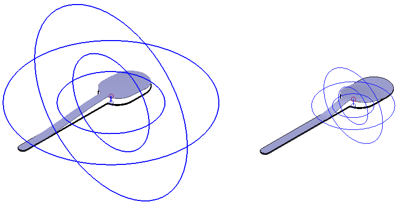
Altering the size of the outer sphere changes the extent of the morph a shown below:
Altering the inner sphere affects the shape of the morph. Decreasing the size of the inner sphere makes the morph more angular; increasing the size of the inner sphere produces a more rounded bulge.
To avoid introducing folds in the solid, the radius of the outer sphere should be at least twice the distance from the origin to the distortion point.
- Select the Move normal to surface option so that the position of the distortion point (To) can lie only along a line normal to the surface at the origin point. Deselect this option to select the distortion point away from the line normal to the surface. If the origin (From) you selected lies on the surface of the model, this option is selected automatically.
- Select the Limit using plane option to replace the bounding spheres with a limiting plane. The orientation of the plane is defined by the selected principle axis of the active workplane. You can drag the boundaries of the plane to adjust its position.
- The model is updated as you make changes. Click Preview to refresh the view if you distort the model by a large amount, to ensure the model reflects all the changes.
- Click OK to create the morph.