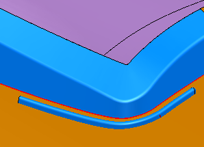
A Drawbead surface is a ridge constructed to hold the metal in position during the forming process. It is often created at the corners of the part:
- Select Surface tab > Manufacture panel > Tooling > Drawbead to display the Drawbead Creation dialog.
- Use the options in the dialog to define the drawbead:
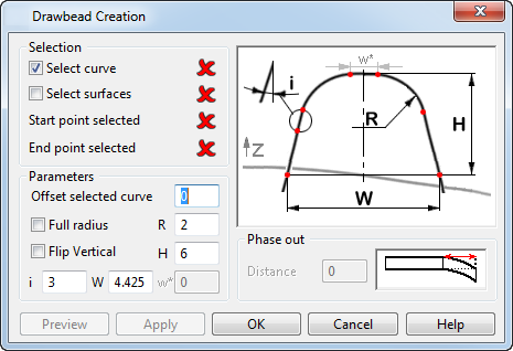
Selection — The options in this section let you choose the curve, surface and points to be used to create the Drawbead surface:
- Curve selected — Select this option and then select the curve to be used.
- Surface selected — Select this option and then select the surface to be used.
- Start point selected — The icon changes from
 to
to
 , indicating the start point has been selected.
- End point selected — The icon changes from
to
, indicating the end point has been selected.
Parameters — The options in this section let you change the shape and size of the Drawbead surface by adjusting parameters:
- Offset selected curve — The selected curve is offset by the value you enter.
- Full Rad — Select this option to apply the radius R to the profile, and set w* to zero.
- R — Radius of the profile.
- Flip Vertical — Select this option to create the Drawbead in the -Z direction.
- H — Height of the profile.
- i — Angle of the side of the profile.
- W — Width of the base of the profile.
- w* — Width of the top of the profile. This is automatically set to zero if Full Rad is selected.
Preview — Select to preview the results. You may make changes and preview again.
Apply — Select to apply the results.
Phase out — This tapers off the end of the Drawbead surface over a specified distance:
Distance — Specify the distance over which the phase out occurs.
- When the Drawbead is correct, click OK.