This method lets you sketch a curve on or around the model, and deform the curve to change the shape of the model. Alternatively, you can select two appropriate curves. This method gives you more control over the shape of the resulting bulge than the point method.
Use the Curve tab of the Morph dialog to select the curve and specify the morph:
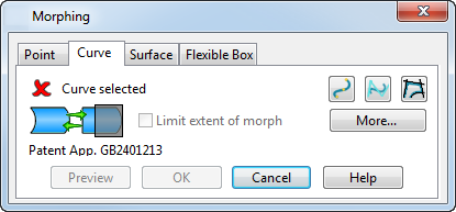
- Select or create a curve on or around the model. This curve is called the reference curve and can be edited to bend or stretch the model. If a suitable curve already exists, it can be selected as normal. Otherwise, create a suitable curve using the curve buttons on the dialog:
 — Create a
Bézier curve to define the morph.
— Create a
Bézier curve to define the morph.
 — Create a
B-spline curve to define the morph.
— Create a
B-spline curve to define the morph.
 — Trace a curve to define the morph.
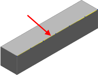
For example, the block model below has a reference curve sketched along one edge:
- When sketching the curve, the Sketch curve dialog is displayed. Select Finish on this dialog to complete the curve and start dynamic morphing.
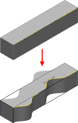
- Click a point on the curve and use the curve handles to change the shape of the curve.
The distortion is applied so that the points on the original curve are moved to the corresponding point on the edited curve and the model is distorted in a similar way. The graphics update when the curve handles are released. The original model is displayed in wireframe and the distorted model in shaded graphics.
- Select the
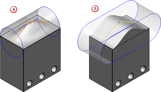
Limit extent of morph option to morph a localized region of the model, while keeping the rest of the model unchanged.
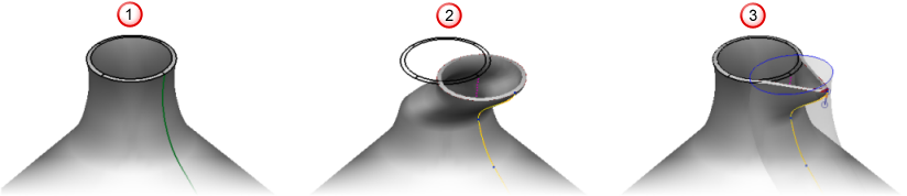
A translucent cylinder or a pair of parallel planes indicate the affected region of the model. You can drag these indicators to change the affected region and the shape of the model. The model below shows the effect of using this option:
- The original model
 .
.
- Distortion with
Limit extent of morph deselected
 .
.
- Distortion with
Limit extent of morph selected
 .
.
- The original model
- Click
More to display additional options on the dialog relating to the shape of the distortions created when the morph is limited:
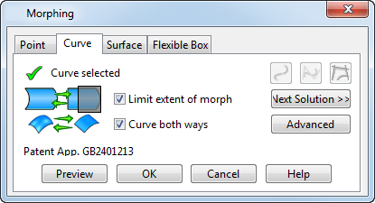
- Select the
Curve both ways
option to curve the model in two directions relative to the curve
 . Deselect this option to keep the distortion constant along an axis controlled by the current principal plane
 . If there are no workplanes in the model, the
World workplane is used.
. If there are no workplanes in the model, the
World workplane is used.
- Click Next Solution to cycle through a number of different possible shapes for the bulge that has been generated by applying limits to a distortion. Step through the four possible solutions and select the one that is best for your needs.
- Click Advanced to display additional options that let you separately select the two curves to be used in morphing. In addition, it allows you to use a curve or surface to limit the region that is affected by the morph.
- The model is updated dynamically as you make changes. Click Preview to refresh the view if the model is distorted by a large amount, to ensure the model reflects all the changes.
- Click OK to create the morph.
 .
.