Use the Workplane dialog to edit a workplane.
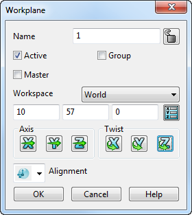
Name — Enter the name of the workplane. The name of the workplane is used in macros to identify it.
Active — Select this option to activate the workplane.
Master — Select this option to make the workplane the Master workplane.
Group — Select this option to group the workplane.

 Lock/Unlock — Use these toggle buttons to lock or unlock the workplane.
Ensure that the
Locked
icon is displayed to lock a workplane. You cannot delete or edit a locked workplane. This is useful if a workplane is set up for a specific purpose and you want to avoid accidentally changing it.
When you lock a workplane, its graphical handles and the options on the Workplane dialog are unavailable.
Ensure that the
Unlocked
icon is displayed to unlock a workplane.
The following section of the dialog contains the plane editing options.
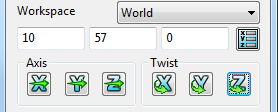
These options enable you to:
- define the workspace in which to edit the workplane.
- move the workplane's origin.
- change the direction of the workplane's axes.
- twist the workplane about its axes.
Plane-editing options are also used in dialogs of other items such as primitive surfaces.
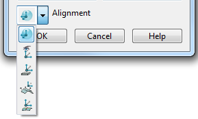
Alignment — Select the alignment of the workplane from the list:
 Aligned — Select this option to align the Z axis of the workplane with the tangent of the object at the clicked point:
- Open the Workplane dialog.
- Select the
Aligned
option from the
Alignment list.
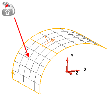
- Click a point on the wireframe.
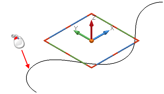
The workplane is aligned as shown below:

If the object is a surface or a solid, the Z axis of the workplane aligns with the normal at the clicked point.
You can snap to points within patches by using
 on a point on a surface like the one below:
The workplane is aligned as shown below:
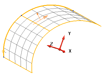
The workplane does not move, it rotates its axes.
 View — Select this option to align the XY plane of the workplane with the current view.
 Minimal Depth — Select this option to align the workplane so that the workplane is set at the minimum depth of the geometry:
- Select the
Minimal Depth
option from the
Alignment list on the
Workplane
dialog.
The Align with minimal depth dialog is displayed:
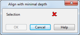
- Select the objects to be used for the workplane orientation.
- Click OK to align the workplane with the minimum depth of the selection.
 Average Normal — Select this option to align the workplane to the average normal of the selected geometry:
- Select the
Average Normal
option from the
Alignment list on the
Workplane
dialog.
The Align with average normal dialog is displayed:

- Select the objects to be used for the workplane orientation.
- Select
Surface area to prioritise the surface area of the surfaces in the selection, over the number of surfaces. In the below example, there are 2 large surfaces, and three minor surfaces in the selection:
If Surface area is selected, the average normal of the selection is indicated by
 .
.
If Surface area is deselected, the average normal of the selection is indicated by
 .
.
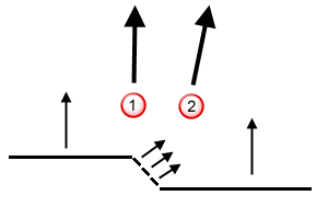
- Click OK.
 Control Section — Select this option to align the workplane with a control section to minimise undercuts:
- Select the
Control Section
option from the
Alignment list on the
Workplane
dialog.
The Align with control sections dialog is displayed:
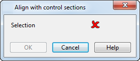
- Select the objects to be used for the workplane orientation.
- Click OK to align an existing workplane with a section.
OK — Saves the edits carried out on the workplane and closes the dialog.
Cancel — Closes the dialog without saving any changes.