You can create extruded surfaces from single or multiple wireframe or text objects.
To create an extruded surface:
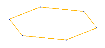
- Select the wireframe or text objects you want to extrude.
The example below shows a wireframe polygon:
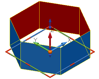
- Click Surface tab > Create panel > Extrusion.
If a single wireframe or text object is selected, it is extruded to form a surface:
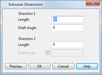
If multiple wireframe or text objects were selected, the Extrusion Dimensions dialog is displayed. This dialog allows you to set the dimensions of the extruded surfaces.
For example:
- Select the following wireframe objects:

- Input the following values for the extruded solids:
Direction 1 - Length — This is the length of the extrusion. The Length of the extrusion can be zero if the Direction 2 - Length has a value other than zero.
Draft Angle — This is the draft angle between the base curve of the extruded solids and the curve at the other end. The angle is measured from the axis normal to the principal plane or the plane of best fit of the curve.
Direction 2 - Length — The length of the extrusion below the active plane.
- Click
Preview to see the extruded surfaces:
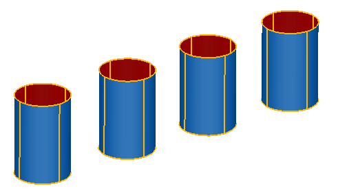
You can change the Length and Draft Angle values and click Preview again to update the surfaces:
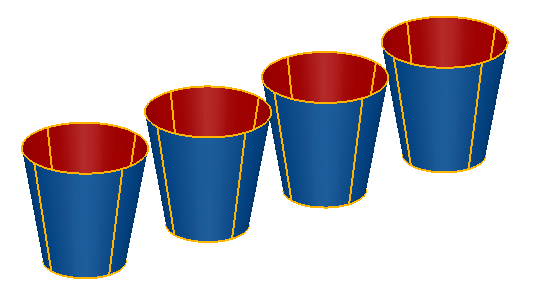
- Click OK to accept the surfaces that you have previewed and close the dialog.
For information on editing an extruded surface, see Graphically editing primitives.
If the wireframe or text is non-planar, the extrusion is in the positive direction of the axis normal to the principal plane. If the wireframe or text is planar, the extrusion is normal to the plane in which the wireframe or text lies. You can change this default by deselecting the Create extrusions normal to planar base option on the File > Options > Application Options > Object > Surfaces dialog.
The wireframe or text used to create the extruded surface is removed from the model by default. You can add the wireframe or text to the model again using the Sketch tab of the Extrusion dialog. This is displayed by double-clicking the surface. To keep the wireframe or text in the model whenever you create an extruded surface, select the Keep Wireframe option on the File > Options > Application Options > Object > Surfaces dialog.