Converts an AutoCAD block to a piping component by adding ports.
Access Methods
 Command entry:
plantpartconvert
 Summary
You can convert an AutoCAD block to a block-based piping component by specifying port locations and directions. After ports are set, you can use the block in the Custom Parts Window to create a block-based component.

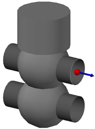
The port indicator displays port location and orientation for custom piping components.
You can also add the block-based component to a catalog. After the component is added to a catalog, you can add it to a spec. For more information, see Catalog Editor - Create New Component (Block Based).
Valve Operators (Actuators)

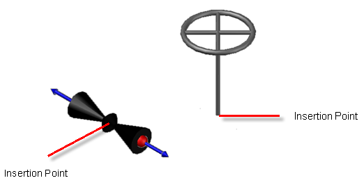
When creating a valve actuator, set the insertion point of the actuator to match the insertion point of the valve body. In plantpartconvert, select the actuator block and use the Exit option. Because an actuator has no ports, you do not use the Add option.
If you set block object color to BYBLOCK, the component supports automated layer and color assignment.
Pipe Supports

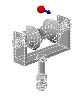
Block-based pipe supports have a single port that aligns with piping centerline.
List of Prompts
Select block to convert. Select an AutoCAD block or a converted part.
Choose modification for port [Add/Delete/Move/eXit]:
Choose modification for port [Flip/Undo/Accept]:
Accept
Saves port edit changes following an Add, Move, or Delete.
Add
Adds a port to the part. You add one or more ports to a part.
Delete
Removes a port.
Exit
Saves changes and ends the command.
On exit, XML and PNG files are created in the drawing folder. These files are required when creating a block based component from the drawing. If you copy the drawing to another location, include these files.
It is highly recommended that you save the current drawing immediately after Exit. Saving guarantees that the supporting XML and PNG files match the DWG.
Flip
Reverses the port direction. Ports should face outward. Port direction is needed to support a piping connection. Port direction does not indicate process flow.
Move
Specifies a different port location. Use this option when the default location is not correct.
Undo
Saves changes to the port following an Add, Move, or Delete.