When you create a path of travel, Revit analyzes the current view and calculates an optimum (shortest) path. During calculations, Path of Travel avoids categories identified as obstacles (defined in settings) and accounts for the width of a typical person and body sway while walking.
Path of Travel analysis is based on the Simulex analysis engine. It is performed in 4 steps:
- Define a grid and generate a preliminary route.
- Find the nearest obstacles along the preliminary route.
- Use corner snap points to generate a modified path.
- Offset from obstacles to generate an optimal "walking" path.

These steps are internal processes to the analysis. The following sections describe the steps to clarify how the path line is generated.
Generate a route
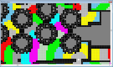
To begin a Path of Travel analysis, Revit applies a grid to the plan view. The grid resolution is fixed to 0.2 meters. Each grid cell is given a value related to the distance from the end point of the path. Colors in the image indicate distance ranges.
Cells containing categories defined as obstacles are removed from consideration (shown as black in the image.) If a cell is bordered on 2 sides by these removed cells, that cell is also removed from consideration. The following image shows this condition between some tables. The condition may affect an analysis when spaces are very narrow.
| Grids and distances |
|
Based on these initial calculations, Revit generates a preliminary path, creating nodes through the center points of the cells along the shortest path possible. The shortest unobstructed path is determined using a custom form of the A* algorithm.
| Preliminary path |

|
Identify obstacles near preliminary route
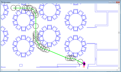
To generate a more optimal path, Revit identifies obstacles near the preliminary path. To find nearby obstacles, a 0.3-meter radius circle is placed at each node along the preliminary path. The nearest intersection of an obstacle with the circle is identified as a corner snap point for the modified path.
| Locate nearby obstacles |
|
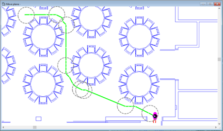
To capture additional corner snap points, Revit performs another pass along the preliminary path. At any nodes where the 0.3-meter radius circles did not intersect obstacles, a larger 0.566-meter radius circle is used to find potential obstacles farther away.
| Locate nearby obstacles 2nd pass |
|
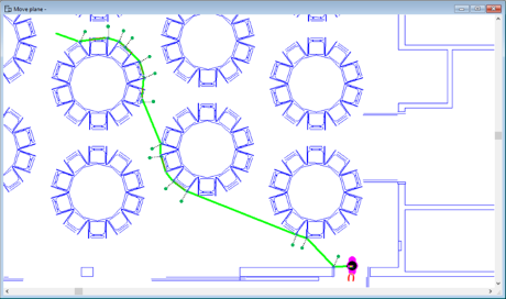
Generate a modified path
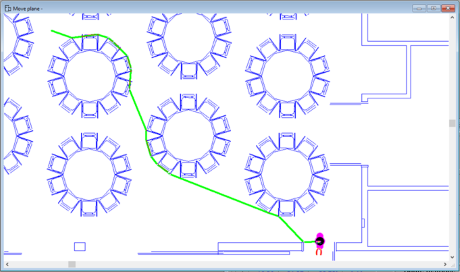
Using those corner snap points, Revit generates a modified path that follows a route as close to obstacles as possible along the preliminary path. This modified path becomes the basis for generating the final path of travel.
| Modified path |
|
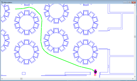
Offset optimal path of travel
Revit offsets each node on the modified path 0.3 meters away from the obstacle (0.25 meters for body radius and 0.05 meters for body sway). The offset projects 90° from the entry/exit angles to the node,with a minimum of 30° between offset points.
| Offset for body width |
|
Offset points that are very close together (less than 0.2 meters) are merged to smooth the final path. Revit draws the final optimized path using the offset points.
| Create final path of travel |
|