Route Analysis settings control how model elements effect the path of travel. Model elements between the starting and ending points of the path of travel will impact the route generated by the analysis.
Obstacles
- Elements hidden in the view.
- Demolished elements.
- Elements visible in an underlay to the view.
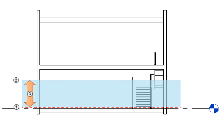
Analysis Zone
The analysis zone used by the path of travel is established by a top and bottom offset value from the views level. If any geometry from a model element is within the analysis zone it will be considered an obstacle to the path of travel. The path of travel will be generated to avoid those obstacles in the path of travel.
As a general rule, it is best to set the top of the analysis zone above the cut plane of the view (see: About the View Range). When the top of the analysis zone is below the cut plane, you may experience unexpected behavior.
The following section shows the analysis zone
![]() of a plan view: Bottom
of a plan view: Bottom
![]() , Top
, Top
![]() .
.