While working with families in the families in the Family Editor, use the Swept Blend tool to create a 3D form based on two 2D profiles and a path segment.
 Video: Create a Swept Blend
The shape of the swept blend is determined by the starting shape, the ending shape, and the 2D path that you specify.
For information about using swept blends in families, see Creating Family Geometry.
About swept blends
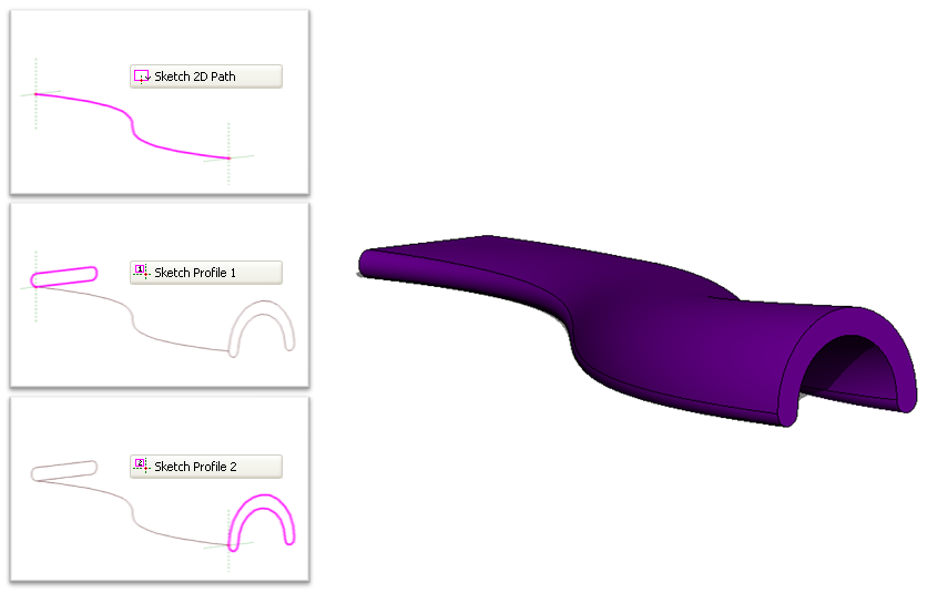
The Swept Blend tool allows you to create a blend that has 2 different profiles and then sweep it along a path. The shape of a swept blend is determined by the 2D path you either sketch or pick and the 2 profiles you either sketch or load.
The following procedure is a general method for creating a swept blend. Steps may vary depending on your design intent.
To create a solid or void swept blend
- In the Family Editor, on the Create tab
 Forms panel, do one of the following:
- To create a solid swept blend, click
 (Swept Blend).
- To create a void swept blend, click Void Forms drop-down
 (Void Swept Blend).
- To create a solid swept blend, click
- Specify the path for the swept blend.
Note: If necessary, set the work plane before you sketch or pick the path for the swept blend. Click Create tabWork Plane panel
 (Set).
Do one of the following on the Modify | Swept Blend tab
Swept Blend panel:
- Click
 (Sketch Path) to sketch a path for the swept blend.
- Click
 (Pick Path) to pick existing lines and edges for the swept blend.
- Click
- Sketch or pick the path.
To select edges of other solid geometry, such as extrusions or blends, click Pick Path. Or pick existing sketch lines, watching the status bar to know what you are picking. This method of picking automatically locks the sketch lines to the geometry you are picking and allows you to sketch the path in multiple work planes, hence allowing for a 3D path.
Note: A swept blend path can only have one segment. - On the Mode panel, click
 (Finish Edit Mode)
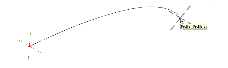
- Load or sketch Profile 1.
The end point for Profile 1 on the swept blend path is highlighted.
- To load a profile:
- Click Modify | Swept Blend tabSwept Blend panel, and select a profile from the Profile drop-down.
If the profile you need is not already loaded in the project, click
 (Load Profile) to load the profile.
- Zoom in to see the profile.
- Use the X, Y, Angle, and Flip options to adjust the position of the profile.
Enter values for X and Y to specify the offset for the profile.
Enter a value for Angle to specify the angle of the profile. The angle rotates the profile around the profile origin. You can enter negative values to rotate in the opposite direction.
Click Flip to flip the profile.
- Click Apply.
- Click Modify | Swept Blend tab
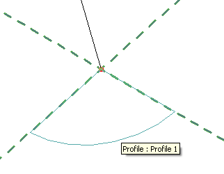
- To sketch a profile:
- On the Swept Blend panel, verify that <By Sketch> is selected and click
 (Edit Profile).
- If the Go To View dialog displays, select the view where you want to sketch the profile, and click OK.
- Use the tools on the Modify | Swept Blend > Edit Profile tab to sketch the profile. Profiles must be closed loops.
- On the Mode panel, click
(Finish Edit Mode).
- On the Swept Blend panel, verify that <By Sketch> is selected and click
- To load a profile:
- Click Modify | Swept Blend tabSwept Blend panel
 (Select Profile 2).
- Load or sketch Profile 2 using the steps above.
- Optionally, edit the vertex connections. By editing vertex connections, you control the amount of twist in the swept blend. You can edit vertex connections in plan or 3D views.
- On the Modify | Swept Blend tabSwept Blend panel, click
 (Edit Vertices).
- On the Edit Vertices tabVertex Connect panel, select
 (Controls on Base) or
 (Controls on Top).
- In the drawing area, click the blue controls to move the vertex connections.
- On the Vertex Connect panel, click the
 (Twist Right) and
 (Twist Left) tools to twist the swept blend.
- On the Modify | Swept Blend tab
- When finished, click Mode panel (Finish Edit Mode).
- On the
Properties palette, specify the swept blend properties:
- To set the visibility of a solid swept blend, under Graphics, for Visibility/Graphics Overrides, click Edit, and specify the visibility settings.
- To apply a material to a solid swept blend, under Materials and Finishes, click in the Material field, click
 , and specify a material.
- To assign a solid swept blend to a subcategory, under Identity Data, for Subcategory, select a subcategory.
- Click Apply.