Learn about creating documentation for non-perpendicular cut elements.
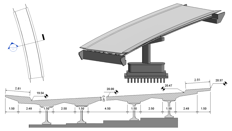
When an element intersects the cut plane of a view and is not perpendicular to that view, you can place dimensions to edges and points in the same way you would to elements perpendicular to the cut plane of the view. As shown in the bridge deck example below, dimensions are placed on the edges and points where they intersect the cut plane of the view.
Note: You cannot constrain (lock) geometry to references created from edges and points created from a cut plane.
When you attempt to select overlying or closely located references, press
Tab to cycle through the available references. Regular references take precedence by default, so cut references will likely require tab selection in such instances. Use the in-canvas tooltips or status bar to determine whether you are selecting the element reference or the cut geometry reference of the element.