Create a reference line that you can use when creating model geometry, or to create constraints for the geometry.
In the Family Editor, you can add a reference line in any view and use the same drawing tools and techniques used when adding model lines. When you sketch a reference line, it displays as a single line.
In a view where the visual style is set to hidden line or wireframe, the sketched line displays as a solid line and the plane extents display with dashed lines.
Reference lines are rotatable, while reference planes are not. If you want to rotate and element or subcomponent family, it is recommended that you use reference lines.
Additionally, reference lines allow you to adjust endpoints on angles when there is a known length.
To add a reference line
- In the Family Editor, click Create tab
 Datum panel
 (Reference Line).
- Using the drawing tools, sketch the line.
The line displays as a solitary solid line until selected or when highlighted during preselection.
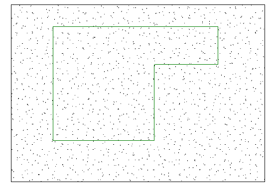
Example of reference lines sketched as a polygon
When selected or highlighted, the associated planes display according to the active view.
- To use reference lines and linear dimensions to control model geometry:
- Align the face of a model element to the reference line and lock it.
- Add a dimension line referring to the reference line and label it as an instance or type parameter.
- Flex the model by changing and applying a new value within the Family Types dialog.