Parameters for Nonlinear Static Analysis Control
Description: Defines a set of parameters for nonlinear static analysis.
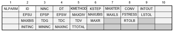
Format:
Example:

| Field | Definition | Type | Default |
|---|---|---|---|
| ID | Identification number. | Integer > 0 | Required |
| NINC | Number of increments. See Remark 2. | Integer > 0 | See Remark 2 |
| DT | Incremental time interval for creep analysis. See Remark 3. | Real ≥ 0 | 0.0 |
| KMETHOD | Method for controlling stiffness updates, one of the following character variables: AUTO, ITER, or SEMI. See Remark 4. | Character | AUTO |
| KSTEP | Number of iterations before stiffness update for the ITER method. See Remark 5. | Integer > 0 | 5 |
| MAXITER | Limit on number of iterations for each load increment. See Remark 6. | Integer > 0 or AUTO | AUTO |
| CONV | Convergence criteria, one of the following character variables: U, P, or W, or any combination. See Remark 7. | Character | PW |
| INTOUT | Intermediate output request, one of the following character variables: YES, NO, or ALL, or the load increment interval for output. See Remark 8. | Character or Integer > 0 | NO |
| EPSU | Error tolerance for displacement (U) criterion. | Real > 0.0 | See Remark 17 |
| EPSP | Error tolerance for load (P) criterion. | Real > 0.0 | See Remark 17 |
| EPSW | Error tolerance for work (W) criterion. | Real > 0.0 | See Remark 17 |
| MAXDIV | Limit on probable divergence conditions per iteration before the solution is assumed to diverge. See Remark 9. | Integer > 0 | 3 |
| MAXUBIS | Maximum number of iterations for an upward load increment adjustment. Applicable when the load increment is bisected or the adaptive load increment/convergence method is used. See Remark 16. | Integer > 0 | See Remark 16 |
| MAXLS | Maximum number of line searches for each iteration. See Remark 10. | Integer ≥ 0 | 5 |
| FSTRESS | Fraction of effective stress ( ) used to limit the subincrement size in nonlinear material routines. See Remark 11. ) used to limit the subincrement size in nonlinear material routines. See Remark 11.
|
0.0 < Real < 1.0 | 0.2 |
| LSTOL | Line search tolerance. See Remark 10. | 0.01 < Real ≤ 0.9 | 0.2 |
| MAXBIS | Maximum number of bisections allowed for each load increment. See Remark 12. | Integer > 0 | 5 |
| TDG | Terminate on displacement grid point identification number. See Remark 13. | Integer > 0 | |
| TDC | Terminate on displacement component number. See Remark 13. | 0 ≤ Integer ≤ 6 or MAXT or MAXR | MAXT |
| MAXT Resultant of translation displacement components. MAXR Resultant of rotational displacement components. | |||
| TDV | Terminate on displacement value. See Remark 13. | Real | |
| MAXR | Maximum ratio for the adjusted arc-length increment relative to the initial value. See Remark 14. | 1.0 ≤ Real ≤ 40.0 | 20.0 |
| RTOLB | Maximum value of incremental rotation (in degrees) allowed per iteration to activate bisection. See Remark 15. | Real > 0.0 | 20.0 |
| INITINC | Initial load increment. See Remarks 2 and 16. | 0.0 < Real < 1.0 | 1/NINC |
| MININC | Minimum load increment. See Remarks 2 and 16. | 0.0 < Real < 1.0 | INITINC |
| MAXINC | Maximum load increment. See Remarks 2 and 16. | 0.0 < Real < 1.0 | INITINC |
| TTOTAL | Total time for creep analysis. See Remark 3. | Real ≥ 0 | 0.0 |
Remarks:
- The NLPARM entry must be selected with the Case Control command NLPARM = ID. Each solution subcase requires an NLPARM command.
- In cases of static analysis (DT = 0.0), NINC is the number of equal subdivisions of the load change defined for the subcase. Applied loads, gravity loads, temperature sets, enforced displacements, etc. define the new loading conditions. The differences from the previous case are divided by NINC to define the incremental values. In cases of creep analysis (DT > 0.0), NINC is the number of time step increments. When NINC is blank, the adaptive load increment/convergence method is used with INITINC, MININC, and MAXINC set to the following values:
Variable Value INITINC 1.0E-2 MININC 1.0E-3 MAXINC 0.3 - The units for DT and TTOTAL must be consistent with the units used on the CREEP entry that defines the creep characteristics. TTOTAL specifies the total creep time for the subcase. When the fixed load increment/convergence method is used and TTOTAL is blank, DT is multiplied by NINC to determine total creep time for the subcase. When the adaptive load increment/convergence method is used and TTOTAL is blank, DT is multiplied by INITINC to determine total creep time for the subcase.
- The stiffness update strategy is selected in the KMETHOD field.
- If the AUTO option is specified, the program automatically selects the most efficient strategy based on convergence rates. At each step the number of iterations required to converge is estimated. Stiffness is updated, if (i) the estimated number of iterations to converge exceeds MAXITER or (ii) the solution diverges. See Remarks 7 and 9 for diverging solutions.
- If the SEMI option is selected, the program for each load increment (i) performs a single iteration based upon the new load, (ii) updates the stiffness matrix, and (iii) resumes the normal AUTO options.
- If the ITER option is selected, the program updates the stiffness matrix at every KSTEP iterations and on convergence if KSTEP ≤ MAXITER. However, if KSTEP > MAXITER, the stiffness matrix is never updated. Note that the Newton-Raphson iteration strategy is obtained by selecting the ITER option and KSTEP = 1, while the Modified Newton-Raphson iteration strategy is obtained by selecting the ITER option and KSTEP = MAXITER.
- For AUTO and SEMI options, the stiffness matrix is updated on convergence if KSTEP is less than the number of iterations that were required for convergence with the current stiffness.
- The number of iterations for a load increment is limited to MAXITER. If the solution does not converge in MAXITER iterations, one of two actions is taken depending on the BISECT model parameter. If the BISECT model parameter is set to ON, the load increment is bisected and the analysis is repeated. If the load increment cannot be bisected (i.e. MAXBIS is attained), execution terminates with a fatal error. If the BISECT model parameter is set to OFF, the analysis is continued to the next load increment. (See Section 5, Parameters, for more information on BISECT.) The default AUTO setting uses an initial MAXITER value of 40 and automatically increases this value if the solution appears near convergence.
- The symbols (U for displacement error, P for load equilibrium error, and W for work error) and the tolerances (EPSU, EPSP, and EPSW) define the convergence criteria. All the requested criteria (combination of U, P, and/or W) are satisfied upon convergence.
- INTOUT controls the output requests for displacements, element forces and stresses, etc. YES, ALL, or the load increment interval for output must be specified in order to output intermediate (incremental) results.
INTOUT Output Processed YES For every computed load increment excluding bisected and quadsected load increments NO For the last load of the subcase ALL For every computed load increment including bisected and quadsected load increments n For computed load increments n , 2 * n , 3 * n ,…, and the last converged increment - For the Newton-Raphson iteration method (i.e., when no NLPCI Bulk Data entry is specified), the option ALL is equivalent to option YES since the computed load increment is always equal to the user-specified load increment.
- For arc-length methods (i.e., when the NLPCI Bulk Data entry is specified), the computed load increment in general is not going to be equal to the user-specified load increment and is not known in advance. The option ALL allows the user to obtain solutions at the desired intermediate load increments.
- The ratio of energy errors before and after the iteration is defined as divergence rate
 , i.e.,
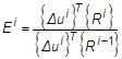
Depending on the divergence rate, the number of diverging iterations (NDIV) is incremented as follows:
- If
 or
or
 , then NDIV = NDIV + 2
- If
 , then NDIV = NDIV + 1
The solution is assumed to diverge when NDIV ≥ MAXDIV. If the solution diverges and the load increment cannot be further bisected (i.e., MAXBIS is attained), execution terminates with a fatal error.
- If
- The line search is performed as required if MAXLS > 0. The line search procedure scales the displacement increment to minimize the energy error. The procedure is skipped if the absolute value of the relative energy error is less than the value specified by LSTOL.
- The number of subincrements in the material routines is determined so that the subincrement size is approximately FSTRESS *
(equivalent stress).
- The number of bisections for a load increment is limited to MAXBIS. If the solution diverges, the stiffness is updated on the first divergence and the load is bisected on the second divergence.
- When TDG, TDC, and TDV are specified, the solution will proceed until either the entire load is applied or the specified displacement value (TDV) at grid point TDG in direction TDC is reached or exceeded. Displacements are in the displacement coordinate system of the TDG grid point.
- MAXR is used in the adaptive load increment/arc-length method to define the overall upper and lower bounds on the load increment/arc-length in the subcase using the relation:
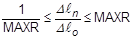
where
 is the arc-length at step
n and
is the arc-length at step
n and
 is the original arc-length. The arc-length method for load increments is selected by an
NLPCI Bulk Data entry. This entry must have the same ID as the NLPARM Bulk Data entry.
is the original arc-length. The arc-length method for load increments is selected by an
NLPCI Bulk Data entry. This entry must have the same ID as the NLPARM Bulk Data entry.
- The load increment is bisected if the incremental rotation for any degree of freedom
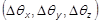 exceeds the value specified by RTOLB. This bisection strategy is based on the incremental rotation and controlled by MAXBIS.
- INITINC, MININC, and MAXINC are used in the adaptive load increment/convergence method to define the overall upper and lower bounds on the load increment in the subcase. INITINC specifies the initial load increment and replaces the value determined using NINC. When MININC < INITINC < MAXINC, the load increment is adjusted up or down based on convergence and solution stability. MAXUBIS defines the maximum number of iterations for the load increment to be adjusted upward or downward. If the number of iterations in an increment is below this value, the load increment is doubled and if greater than twice this value, the load increment is halved. INITINC, MININC, and MAXINC are not applicable when arc-length methods are specified via the NLPCI Bulk Data entry. When adaptive loading is not used, MAXUBIS defines the maximum number of iterations for the load increment to be adjusted upward during bisection.
- Default tolerance sets are determined based on solution type, nonlinear behavior requested, and desired accuracy. Accuracy is under user control and can be specified using PARAM, NLTOL (see Section 5,
Parameters, for more information on
NLTOL). The NLTOL values are only used if one or more of the EPSU, EPSP and EPSW fields on the NLPARM entry are blank. The following tables show the tolerance values used depending on the NLTOL parameter setting specified.
-
Nonlinear Static Analysis without Contact and Material Nonlinearity
NLTOL Level of Accuracy EPSU EPSP EPSW 0 Very High 1.0E-3 1.0E-3 1.0E-6 1 High 1.0E-2 1.0E-2 1.0E-4 2 Engineering 1.0E-2 1.0E-2 1.0E-3 3 Preliminary Design 1.0E-1 1.0E-1 1.0E-2 Default Engineering 1.0E-2 1.0E-2 1.0E-3 - Nonlinear Static Analysis with Material Nonlinearity
NLTOL Level of Accuracy EPSU EPSP EPSW 0 Very High 1.0E-4 1.0E-4 1.0E-8 1 High 5.0E-4 5.0E-4 1.0E-8 2 Engineering 5.0E-4 5.0E-4 1.0E-7 3 Preliminary Design 1.0E-3 1.0E-3 1.0E-6 Default Engineering 5.0E-4 5.0E-4 1.0E-7 - Nonlinear Static Analysis with Contact
NLTOL Level of Accuracy EPSU EPSP EPSW 0 Very High 1.0E-3 1.0E-3 1.0E-6 1 High 1.0E-3 1.0E-3 1.0E-5 2 Engineering 5.0E-3 5.0E-3 1.0E-4 3 Preliminary Design 5.0E-3 5.0E-3 1.0E-4 Default Engineering 5.0E-3 5.0E-3 1.0E-4 - Nonlinear Steady State Heat Transfer
NLTOL Level of Accuracy EPSU EPSP EPSW 0 Very High 1.0E-3 1.0E-3 1.0E-6 1 High 1.0E-3 1.0E-3 1.0E-6 2 Engineering 1.0E-3 1.0E-3 1.0E-6 3 Preliminary Design 1.0E-3 1.0E-3 1.0E-6 Default Engineering 1.0E-3 1.0E-3 1.0E-6
-
Nonlinear Static Analysis without Contact and Material Nonlinearity