To Work with General Annotations
Use the General Annotation commands to add dimensions, hole notes, and surface texture symbols to the 3D model.
What's New: 2023, 2024.1
Before you begin, set the units in Document Settings, Standards tab, and then select the desired standard in the Annotations, Active Standard drop-list.
Add or edit dimensions
On the ribbon, click Annotate tab
 General Annotation panel Dimension
  .
.Select the geometry to dimension.
Optionally, do any of the following and then click to place the dimension:
- Click Change Annotation Plane in the context menu, or use the SHIFT shortcut key, and then select an alternate annotation plane.
- Click Change to Next Candidate Plane in the context menu or use the SPACEBAR shortcut to cycle through alternate planes.
Click the drop-list in the minitoolbar and select the dimension style, such as Basic.
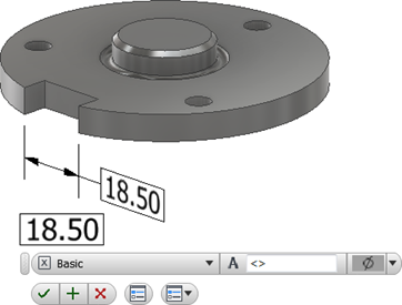
Optionally, do any of the following:
- Place your cursor in the value box and then add prefix or suffix to the value.
- To access more options, click Edit Dimension in the minitoolbar to display the dialog box and then make any required changes.
Click OK to add the dimension.
To edit a dimension:
Select the dimension in the display or browser, right-click, and select Edit in the context menu.
Double-click the dimension in the display or browser.
Change the required dimension values and then click OK.
Extract existing dimensions
To include existing dimensions in the model-based definition:
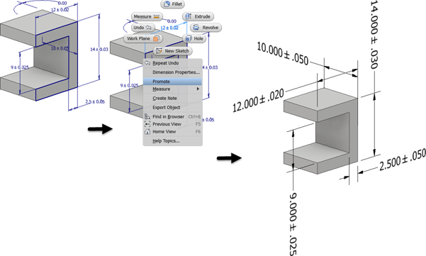
Right-click a feature in the browser and select Show Dimensions.
Click any visible dimension and select Promote in the context menu to create a 3D annotation.
If the model dimension includes tolerance information, it is included in the promoted dimension.
 If you edit the promoted 3D annotation, check Synchronize parameters tolerance to apply tolerance changes to the sketch dimension. Clear the check to change the 3D annotation tolerance without changing the sketch dimension.
Editing Annotation Leaders
You can modify annotation leaders by adding or deleting vertices.
Right-click the annotation browser node or the annotation in the canvas and select:
- Add Vertex to increase the number of vertices, used to change the leader shape, in the leader.
- Delete Vertex to decrease the number of vertices in the leader.
Vertices that are added display on the leader. Click and drag to reposition them.
When deleting a vertex, after selecting Delete Vertex, click on the vertex you want to remove.
Add or edit hole/thread notes
Holes and threads annotated by a hole/thread note cross-highlight when you select the leader or the browser node.
On the ribbon, click Annotate tab
General Annotation panel Hole/Thread Note  .
.Select the hole feature.
Optionally, do any of the following and then click to place the hole note:
- Click Align to Geometry in the context menu and then select an edge or axis to orient the text.
- Click Change Annotation Plane in the context menu, or use the SHIFT shortcut key, and then select an alternate annotation plane.
- Click Change to Next Candidate Plane in the context menu or use the SPACEBAR shortcut to cycle through alternate planes.
Optionally, do any of the following:
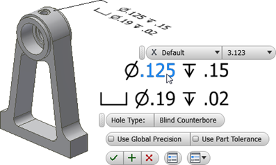
Enable the Use Global Precision checkbox or clear the checkbox and then click a drop-list value to change the precision.
Enable the Use Part Tolerance checkbox or clear the checkbox and then click a drop-list value to change the tolerance.
To access more options, click Edit Hole Note in the minitoolbar to display the dialog box and then make any required changes.
Click OK to add the hole/thread note.
To edit a hole/thread note:
Select the hole/thread note in the display or browser, right-click, and select Edit in the context menu.
Double-click the hole/thread note in the display or browser.
Change the required values and then click OK.
Add or edit surface texture symbols
Surface Texture annotations are created with a single-segment leader by default. To create more leader segments, start the command, right-click, and click Single-Segment Leader to unselect the option.
On the ribbon, click Annotate tab
General Annotation panel Surface Texture  .
.Select a model face.
Optionally, do any of the following and then click to place the surface texture annotation:
- Click Align to Geometry in the context menu and then select an edge or axis to orient the text.
- Click Change to Next Candidate Plane in the context menu or use the SPACEBAR shortcut to cycle through alternate planes.
Optionally, do any of the following:
Click the drop-list and select the desired surface texture symbol.
Click a checkbox next to Force tail, Majority, or All-around to modify the symbol.
To access more options and Presets, click Edit Surface Texture Symbol in the minitoolbar to display the dialog box and then make any required changes.
Edit Surface Texture Symbol is located here
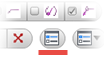 in the minitoolbar. For more on presets, see To Work with Presets.
Click a letter to enable a value box, add the required finish values, and then click OK to create the symbol.
To edit a surface texture symbol:
Select the surface texture annotation in the display or browser, right-click, and select Edit in the context menu.
Double-click the surface texture annotation in the display or browser.
Change the required values and then click OK.

Add or edit welding symbols
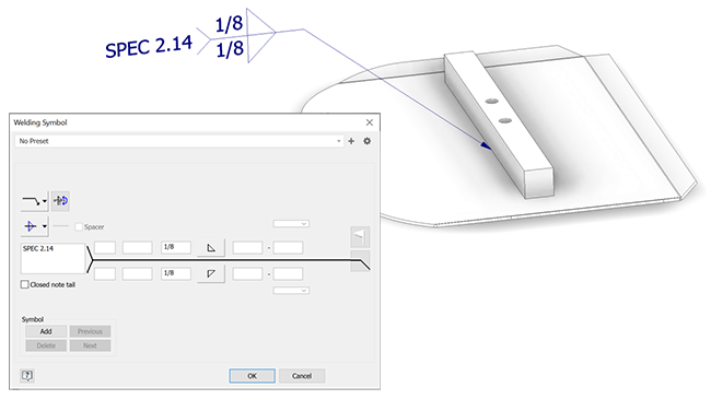
On the ribbon, click Annotate tab
General Annotation panel Welding Symbol 
Select the geometry where you want the weld symbol to anchor.
- If an edge, after placement, you can move the anchor point along the edge to adjust its position.
- If a face, after placement, you can move the anchor anywhere within the face boundary.
During preview, use the following to change the annotation plane (Shift) and alignment (Tab).
Click to position the leader.
Right-click and click Continue to define the weld symbol.
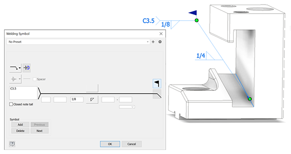
In the Welding Symbol dialog, set the features you want represented by the symbol.
Optionally, to include subwelds use these Symbol options:
Add, extends the leader and adds a secondary symbol set.
Delete, removes the current symbol set whether primary, secondary, or other.
Next, makes the next symbol in the group active for editing or deleting.
Previous, makes the previous symbol in the group active for editing or deleting.
To use 3D model annotations in a drawing, see Retrieve model annotations in a drawing.
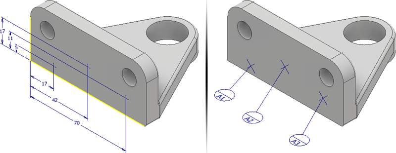
Add or edit datum targets
To precisely position datum targets, do either of the following:
- Start a 2D sketch, place sketch points and then add locating dimensions.
- Create and position Work Points.
Optionally, before you start the command create 2D sketch points or place Work Points.
On the ribbon, click Annotate tab
General Annotation panel Datum Target  .
.If there are no existing 2D sketch points, select the desired Work Points, or click a minimum of three locations on a planar model face. The selected locations should not be in a line.
Optionally, highlight a datum target and do any of the following after you place the datum target annotations:
- Click Toggle Alignment in the context menu or use the TAB shortcut to cycle through the available alignments.
- Click Change Annotation Plane in the context menu and then select a planar face to orient the symbol and text.
- Click Change to Next Candidate Plane in the context menu to cycle though alternate planes.
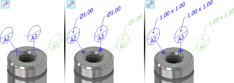
Select a Type:
- Point uses point locations to define the datum target zone.
- Circle establishes a circular datum target zone. Enter the diameter of the target zone. Optionally, clear the check box Apply size to all datum targets, click each target and enter a unique diameter value.
- Rectangle establishes a rectangular datum target zone. Enter the length and width of the target zone. Optionally, clear the check box Apply size to all datum targets, click each target and enter a unique length and width value.
- Click the drop-list to choose a Datum Label. Choose Custom to specify a label that does not appear in the list.
- Click OK to create the datum target.
To edit a datum target, do any of the following:
- Select the datum target annotation in the display or browser, right-click, and select Edit in the context menu.
- Double-click the datum target annotation in the display or browser.
Change the required values in the property panel and then click OK.