Add a feature control frame symbol
On the ribbon, click Annotate tab
 Symbols panel Feature Control Frame .
To place the symbol, do one of the following:
To create a symbol associated to a part edge, pause the cursor over the edge and double-click to add the symbol.
To create a symbol without a leader line, double-click a location for the symbol.
To create a symbol without a leader line associated with geometry, double-click a highlighted edge or point. The symbol is attached to the edge or point.
To create a symbol with a leader line, click a location for the start point of the leader line. If you click a highlighted edge or point, the leader line is attached to the edge or point. Move the cursor and click to add a vertex to the leader line. When the symbol indicator is in the desired position, right-click, and select Continue.
Tip: To edit the position of the frame, pause the cursor over the symbol green dot and click-drag to reposition. A small distance will flip the symbol to the other side of an edge. A larger distance will pull the frame away from the edge and add a leader.Tip: To rotate a feature control frame symbol, right-click the symbol, and click Rotate 90 CW or CCW.
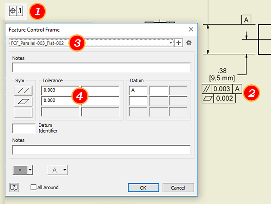
(Optional) Select a symbol preset and modify as needed. If no preset exists, continue with these steps. In step 5 you can save a preset.
Note: If a preset cannot be selected, grayed text, most likely there is an incompatibility between the style settings and the preset content. To use the preset, change either the incompatible content or style setting.Set the attributes and values for the symbol in the Feature Control Frame dialog box, and click OK.
(Optional) If the symbol values are used often, save them as a named preset. To save as a preset, in the preset field click
 and accept the default name or specify one based on your naming conventions.Note: For more details about Presets see To Work with Presets.
Continue placing feature control frames. When you finish placing symbols, right-click, and then choose Done from the menu to end the operation.