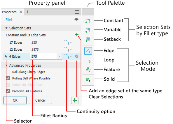
To Create Edge Fillets
Edge fillets and rounds are separated into three behavioral types - Constant, Variable, and Setback.
The fillet command makes it easy to apply fillets and rounds of varying radii and conditions as one feature. The property panel provides fillet types, selection modes, and selection sets to achieve a robust filleting operation. For each fillet type you can have multiple selection sets of differing sizes.
For more information about property panel common controls see About Property Panels
The Fillet property panel has a tool palette that is docked to the side. You can drag it away and detach the two if so desired. To reconnect them, click-and-drag one near the other and when the blue edge appears release the mouse button. When the cursor is near the property panel the side where the tool palette will snap is highlighted.
The tool palette controls enable adding multiple fillet sizes and types in one command session:
- Add different edge fillet selection set types - constant or variable, and create fillet setbacks. To add different selection set type, in the tool palette, click the type you want to use and select the edges for that type. To add fillets with a different radius, add another selection set to the current fillet type.
- You can't create multiple empty sets. Sets must be populated in order to create an additional set of the same type.
- If there is an empty selection set and a different selection set type is selected, the empty set is replaced by the selected set.
- Change selection filter priorities - edge, loop, feature, or solid body.
- Selecting the Solid selection filter will replace an empty selection set.
- Selecting a different fillet type with a Solid selection filter empty deletes the solid selection group and adds the selected filter type.
Input feedback
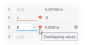
When a value conflicts with other aspects of the feature warning badges appear in the property panel and HUD. Hover the cursor over the badge to view the tooltip information. For example, in the following image two variable fillet edges conflict with one another. Edge 1 position value (1) conflicts with edge 2 position value (0) because the two points are coincident. The values overlap.
Create a Constant-Radius Edge Fillet
Click 3D Model tab
 Modify panel Fillet
  .
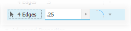
.In the property panel, the Constant Radius Edge Set
 is immediately active. You can begin selecting edges, modify parameters, or change selection set types before you select edges.Note: Use window selection to select multiple edges. Shift+Window to add and Ctrl+Window to remove multiple edges. Use Ctrl+Delete to remove rows of selected edges or click the Clear Selection icon
Switch the Select priority to refine how you select:
 Edge. Adds or removes (Ctrl+click) single edges.
 Loop. Selects or removes the edges of a closed loop on a face.
 Feature. Applies a fillet to all edges of the selected feature that do intersect with other features. If used in the assembly environment, only part features can be selected.
 Solid. Selects all edges of a solid body enabling rapid fillet creation. All body edges share the same radius value.
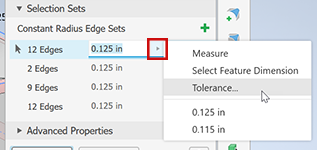
Note: When you have a current select set and change the Select Mode, the current set is retained and a new selection set is created.Specify the fillet radius using the in-canvas manipulator, in-canvas value editor, or the property panel field. To apply tolerances to the fillet radius, click the arrow in the value field and select Tolerance... then, in the dialog set the desired tolerance type and value.
Select a continuity preference:

 Applies Tangent (G1) fillets which are tangent to adjacent faces.
 Applies Smooth (G2) fillets which are curvature continuous to adjacent faces. Applying this option causes changes in curvature to occur gradually, resulting in smoother, more aesthetically pleasing transitions between faces.
 Applies Inverted fillets which are curvature continuous to adjacent faces. Use the Inverted Fillet option to switch between a convex fillet and concave fillet.Note: To apply an inverted fillet to models created in versions prior to Inventor 2019 first restore the model corner so it becomes a selectable edge and then apply the inverted fillet. This may entail editing or removing some features related to the corner.
Advanced Properties - select or clear the options as needed.
- Roll Along Sharp Edges
- When selected, varies the specified radius as needed to preserve the edges of adjacent faces:

- When deselected, maintains a constant radius and extends adjacent faces when necessary:

- When selected, varies the specified radius as needed to preserve the edges of adjacent faces:
- Rolling Ball Where Possible
- When selected, creates an edge fillet defined as if a ball had been rolled along the edge and around the corners:

- When deselected, creates a continuous tangent transition between edge fillets in sharp corners:
- When selected, creates an edge fillet defined as if a ball had been rolled along the edge and around the corners:
- Automatic Edge Chain. Sets the edge selection preference for edge fillets. Select to select all tangent edges automatically when selecting an edge to fillet. To select only the indicated edges, clear the check box.
- Preserve All Features. When selected, checks all features that intersect with the fillet. Their intersections calculate during the fillet operation. When not selected, only the edges that are part of the fillet operation calculate during the operation.
- Roll Along Sharp Edges
Click OK to finish and close the property panel. Click
 Apply to continue applying fillets and rounds.
Create a Corner Setback
Where three edges or more constant radius edges intersect at the same vertex, you can create a corner setback.
Click 3D Model tab
Modify panel Fillet Select the intersecting edges.
In the Constant Radius Edge Set, specify the fillet size.
In the tool palette, click
 Add corner setback. The property panel expands to display the additional input fields.
In the canvas, select the vertex where the edges intersect.
Note: Available vertices have gray dots, hovering over a vertex you see a green dot, when selected a blue dot.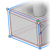
In Corner Setback Behavior, specify the setback distance. The value can be per edge. You can use Tab to move to the next field and Shift+Tab to move to the previous field.
Or, select the Minimal option to allow the command to define the minimum allowable setback for a given vertex selection set. Minimal often provides the smoothest transition and increases the success rate of solving difficult setback fillets.
Optionally, specify the Advanced Properties.
Click OK to finish and close the property panel. Click
Apply to continue applying fillets and rounds.
Create a Variable Radius Fillet
Select one or more edges and specify a different radius for the start point and endpoint of each edge. You can add intermediate points, each of which can have a different radius and position along the edge. Finally, select the edge continuity type.
Click 3D Model tab
Modify panel Fillet In the property panel tool palette, click the
 Variable Radius Fillet. The property panel expands to display the additional input fields.
In the canvas, select one or more edges to fillet. When multiple edges are selected they populate a table in the property panel. The Radius column can be resized and the Position fields can be sorted, the edges remain separated.
To add intermediate points to the edge, pause the cursor along the selected edge at the approximate point location. Click to add the point. In the property panel, the points are ordered based on position value. The point table position updates based on the position values. You can use Tab to move to the next field and Shift+Tab to move to the previous field.
Alternatively, in the property panel, click Add point. The point is placed at midpoint along the edge and the radius is selected for editing. To delete points from the property panel table do one of the following:
- Click the Clear Selections button at the end of a row to delete the point from the input.
- Use Ctrl+Delete to remove the selected row of selection set.
- Pause the cursor over the point and right-click to get the marking menu, then click Delete.
- Pause the cursor over the point and Ctrl+click.
- Pause the cursor over the point and Shift+click.
Note: When you add a variable-radius fillet to a closed loop, such as the end of a cylinder, there are no start and endpoints. Click on the edge to add points and define the positions and radii.You can enter the radius and position of intermediate points as they are added, or add as many as you want and then edit the point table in the property panel.
Note: Each edge has a position 0 (start) to 1 (end). The position value is between 0 and 1.0. Specifying a position value of 0.25 moves the point to one-quarter of the way along the edge.Specify the continuity type. To have edges of differing continuity types, click the
 to create a different selection set for each type.
Specify the Advanced Properties to use.
Smooth Radius Transition. Creates fillets with a gradual blending transition between the points. The transition is tangent (no rate of change between points).

Clear the check box to create fillets with linear transitions between the points.

Click OK to finish and close the property panel. Click
Apply to continue applying fillets and rounds.
All Fillets and Rounds
Apply fillets and rounds to all edges if a solid or multi-body solid. Or, apply only fillets or only rounds as each has a radius parameter. Only one solid selection set can be defined at a time. Use Apply to do multiple solids having different fillet values. Not available in the assembly environment.
Click 3D Model tab
Modify panel Fillet In the tool palette, click the
Solid selection mode. If there is only one solid, it is automatically selected. For a multi-body part, select the target solid.In the Solid selector row, specify how all available edges of the solid body are to be treated:
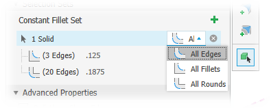
 All Edges (default) - applies both fillets and rounds.
 All Fillets - applies only fillets.
 All Rounds - applies only rounds.
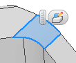
If not automatically selected, select the target solid. The fillets and rounds preview in-canvas, the features preview.
In the property panel, pause the cursor over either selection set to see the participating edges highlighted. Adjust the radius setting as needed. You can clear either selection set if you want to only do rounds or fillets.
Click OK to finish and close the property panel. Click
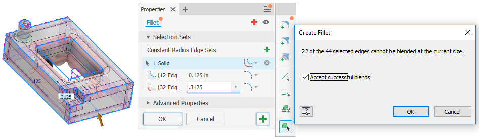
Apply to continue applying fillets and rounds.Note: When some of the edges can't participate, a message explaining how many edges can't participate displays when you click OK or Apply. Accept the conditions or edit the parameters to include more edges.
Tips for using the Fillet command
Take advantage of the edge set capability to create multiple fillets in one step.
- When adding fillets with the same radius to three adjacent edges, use one edge set.
- If there are edges with different radii, use a different edge set for each size. When three different radii intersect the result is a blended corner.

- When two edges have the same radius and the third edge has a different radius, use two edge sets.

- You can switch between edge sets to add or delete edges as needed. To change an edge from one set to another, click into the desired edge set and select the edge you want to change. The edge sets update.
Editing a Fillet Feature
Use one of the following methods to display the feature property panel:
- Select the feature in the canvas and click the Edit HUD
 .
. - In the browser, right-click the feature and choose Edit Feature.
- In the browser, double-click the feature.
- Select the feature in the canvas and click the Edit HUD
In the property panel or with in-canvas manipulators change defining values. To change from edge to face or full round fillets requires deleting and recreating the fillet.
Click OK to finish and close the property panel. Click
Apply to continue applying fillets and rounds.
Fillet Property Panel Tab-key Behavior
For reference in the following, Real Value Edit Controls (RVEC) are referred to by their acronym.
General
- The following cells are ignored when tabbing:
- Label cells
- Disabled cells
- Demoted selectors
- Use Ctrl+Delete to remove rows or field values.
 When a row has focus the selector highlights.
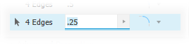 When a value edit cell has focus the value highlights.
- Tab to move progressively to the next field. Use Shift+Tab to move to the previous field.
Constant Fillet rows
- Focus in on the radius RVEC so you can enter a value immediately.
- Tab moves you to the continuity options where you can use the Up and Down arrow keys to select from the list.
- When on the Continuity option the next tab creates a new row.
Setback Fillet rows
- Tab to focus on Setback rows.
- If the selection set is empty, the vertex selector is active and has focus.
- If the selection set is filled, the edge selector and Edge 1 RVEC are active with the focus on Edge1 RVEC.
- Tab moves to RVEC on the next row.
Variable Fillet Rows
Variable Fillet Set
- Tab to focus on Variable Fillet rows.
- If no edge is selected, the edge selector is activated and has focus.
- If an edge is selected, the start point RVEC has focus.
- Variable Set Behavior responds to the Variable Fillet Set row.
Variable Set Behavior
- Tab order is left-to-right, top-to-bottom.
- In the last row's last cell, tab progresses to the next selection set if there is more than one. If only one set, tab progresses to the Advanced Properties.
Up and Down arrow keys
- If an RVEC has focus, these keys move to previous and next RVEC.
- Up and Down work in the context of a single table, for example Setback Set Behavior.
- Use Ctrl+Down arrow to open flyouts.
Fillet Error Messages
At times a message may display stating that the selected edges cannot be blended. The most common occurrence is when there are too many edges selected, or when one set of edges doesn't work with the specified value.
When such an error occurs, try either of these two ways to resolve the issue:
- Select fewer edges and create the fillets. Blending many edges at one time may not always be successful.
- Reduce the fillet size. The size for one or more edges needs to be reduced slightly for the fillet to be successful.
On rare occasion, there may be conditions where the specified size will not work well and the solutions is to iterate on size reduction until successful.