To Edit a Hole Note
Revise text, dimensions, or symbols as required.
In the graphics window, right-click the hole note, and select Edit Hole Note from the menu.
In the Edit Hole Note dialog box, edit the hole note text and other properties:
- Select Use Default to use the default hole note format.
- Optionally, select Tap Drill to display the default format for the Tap Drill hole note in the Edit Field.
- Select Part Units to use model units. Remove the check mark to use the measurement units specified by the dimension style.
- If appropriate, add stacked text. For more information, see To Stack Text in a Drawing. Type a correct stacking sequence, select it, right-click and choose Stack. If Auto Stacking is enabled, fractional numbers with a valid stacking trigger followed by a neutral character are stacked automatically as you type.
- To add tolerance information to values included in the hole note or to override the precision settings, click Precision/Tolerance Settings.
- To create a custom configuration of the quantity note (QTYNOTE property), click Edit Quantity Note.
Edit the hole note text in the edit field. In the Values and Symbols section, click a hole value or a symbol to add the corresponding property to the hole note text.
Click OK to save the changes and close the Edit Hole Note dialog box.
Hide values in a hole or thread note
You can hide the note dimensions and any symbols, values, and text that are added to the hole note by the dimension style.
In the graphics window, right-click the hole note, and then select Hide Value from the menu.
To restore visibility, right-click the hole note, and clear the check mark from Hide Value.
Display or hide alternate unit dimensions
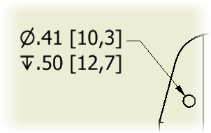
Hole notes can display dimension values both in primary and in alternate measurement units. Edit the Dimension style to change the settings.
Select the Group Dual Values Together option to use adjacent placement of dual dimensions within hole notes.
Change the hole shape and series for a DIN hole note
If you used standard fastener sizes when adding counterbore or countersink hole features in the model, the hole notes include the hole shape and hole series information if the standard style of the hole note is DIN. You can change the hole shape and series.
In the graphics window, right-click the hole note, and then select Hole Shape or Hole Series from the menu.
Click the shape or series to select it.