To Arrange Part Features in Patterns
Create rectangular, circular, and sketch-driven patterns using the property panel. The property panel provides selection and geometry options based on the selected pattern type, selection modes, and direction selectors to specify the position of the pattern.
What's New: 2023.2, 2025, 2026
Key Concepts
- The Property Panel workflow is progressive and flows from top to bottom of the panel. Parameters in a section affect the feature and set the context for the following sections in the panel.
- Rename active pattern from the property panel by clicking the breadcrumb text to select it, then clicking again to edit the text.
- Parameter values can be edited in the property panel, in-canvas, or by clicking-dragging the feature parameter manipulator. Active manipulators highlight in the canvas, and in the property panel the associated field has focus.
- Edited values in the property panel can be committed by pressing Enter or Tab to move to the next field. Press Ctrl+Enter to create the shell and close the property panel.
- Reference dimensions, non-editable, are displayed inside parentheses.
- Preview controls
 are provided during both feature and sketch editing.
The Pattern property panel has a tool palette that is docked to the side. You can drag it away and detach the two if so desired. To reconnect them, click-and-drag one near the other and when the blue edge appears release the mouse button. When the cursor is near the property panel the side where the tool palette will snap is highlighted.
The tool palette enables you to select a pattern type and change selection filter priorities (feature, or solid body).
Input feedback
When a value conflicts with other aspects of the feature warning badges appear in the property panel and HUD. Hover the cursor over the badge to view the tooltip information.
Arrange Part Features or Bodies in a Rectangular Pattern
The Rectangular Pattern tool duplicates features, solids or bodies and arranges the results in a rectangular pattern, along a path, or bidirectionally from the original feature.

Click 3D Model tab
 Pattern panel Rectangular Pattern
  .
.In the tool palette, specify what you want to pattern:
 Patterns a solid body, including features that you cannot pattern individually. Can also include work features and surface features. Not available in an assembly.
 Patterns individual solid features, work features, and surface features. Cannot pattern assembly work features.
In the property panel, the geometry selector is immediately active. You can begin selecting one or more features or bodies to include in the pattern. For parts, you can also select work features and surface features to include in the pattern.
Align selected features in a pattern of rows and columns by specifying the following:
Note: When a work plane or planar face is selected, the normal of the plane is the linear direction.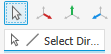 Direction Selects the direction in which to add occurrences. Direction arrow originates at the selection point. Path can be a 2D or 3D line, arc, spline, trimmed ellipse, edge, cylindrical face, or an Origin axis. Path can be an open or closed loop.
 Midplane Creates a pattern where the occurrences are distributed on both sides of the original feature. For rectangular patterns, you can use Midplane independently for either direction (Direction 1, Direction 2).
Number Specifies the number of occurrences in the column or linear path. Must be greater than zero.
Distribution Specifies how distance is measured.
 Incremental Defines the spacing between features. You specify the number of occurrences in the pattern and the distance. The total area occupied by the pattern is calculated.
 Fitted Number of patterns equally fitted to the length of the selected curve. Must be greater than zero.
Distance Specifies spacing or distance between occurrences or distance the column or row spans. A negative value can be entered to create a pattern in the opposite direction.
If desired, click
 to add a member with an irregular distance.
Pattern features within a boundary. The boundary option is only available in part modeling.
Boundary. Click to select a face or a profile that defines the boundary. You can change the boundary at any time, whether face or profile, or no longer use the boundary by deselecting it.
Offset. Offsets the selected boundary creating a keepout area between the boundary line and the offset line. There are three options for patterning inside a boundary. These are:
- Include Geometry All pattern occurrences completely inside the boundary are used for the pattern. The oriented bounding box is used to calculate whether the feature is inside the boundary.
- Include Centroids All pattern occurrences with centroids within the boundary are used for the pattern.
- Base Points Click the base point selector and select a base point on an occurrence. All occurrences with a base point inside the boundary are used for the pattern. To redefine the base point, click the selector
 and select a different point as base point. Note, the selection updates when the new point is selected.
If patterning a solid, choose an operation:
 Join Attaches the pattern to the selected solid body. Patterns the solid as a single, unified body.
 New Solid Creates a pattern consisting of multiple individual solid bodies.
- Set the creation method of the patterned features:
Optimized. Creates identical copies of selected features by patterning feature faces. Optimized is the fastest compute method. Limitations are the inability to create overlapping occurrences, or occurrences that intersect different faces than the faces of the original features. When possible, speeds up the pattern compute.
Identical. Creates identical copies of selected features by replicating the results of original features. When the Optimized method is not possible, use for identical features.
Adjust. Creates potentially differing copies of selected features by patterning features and calculating extents or terminations of each pattern occurrence individually. Computation time is lengthy for patterns with large numbers of occurrences. Preserves design intent by allowing pattern occurrences to adjust based on feature extent or termination conditions, such as a feature that terminates on a model face. Not available for patterns of solid part bodies in an open or surface state.
Note: Patterns created with the Optimized or Identical method calculate faster than the Adjust method. If Adjust encounters a planar face, the pattern terminates. Results are a feature with a size and shape different from the original.
Click OK.
Arrange Part Features or Bodies in a Circular Pattern
The Circular Pattern command arranges occurrences of selected features or bodies into an arc or circular pattern. It duplicates one or more features or bodies and arranges the resulting occurrences by a specific count and spacing in an arc or circle.
Click 3D Model tab
Pattern panel Circular Pattern  .
.In the tool palette, specify what you want to pattern:
- Patterns a solid body, including features that you cannot pattern individually. Can also include work features and surface features. Not available in an assembly.
- Patterns individual solid features, work features, and surface features. Cannot pattern assembly work features.
In the property panel, the geometry selector is immediately active. You can begin selecting one or more features or bodies to include in the pattern. For parts, you can also select work features and surface features to include in the pattern.
Align selected features in a pattern of rows and columns by specifying the following:
Note: When a work plane or planar face is selected, the normal of the plane is the linear direction.- Direction Select the axis (pivot point of angle) about which occurrences should repeat. The axis can be on a different plane from the feature being patterned.
- Midplane Distributes the feature occurrences on both sides of the original feature, which is typically created in a centered location. When the occurrence count is even, use Flip to determine which side gets the extra occurrence.
Count Specifies the number of occurrences in the pattern.
Distribution: Specifies how angle is measured.
 Incremental Defines the spacing between features. You specify the number of occurrences in the pattern and the angle. The total area occupied by the pattern is calculated.
 Fitted Uses an angle to define the total area the patterned features cover. You specify the number of occurrences and the total angle. Spacing between occurrences is calculated. If the design is likely to change, use Fitted positioning, because the spacing of occurrences updates according to design intent.
Angle Angular spacing between occurrences depends on the positioning method. If you select Incremental positioning, the angle specifies the angular spacing between occurrences. If you choose Fitted positioning, the angle specifies the total area the pattern occupies. Enter a negative value to create a pattern in the opposite direction.
Orientation: Specifies the orientation of the pattern.
- Rotational Select if you want the body or feature set to change orientation as it moves around the axis.
- Fixed Select if you want the orientation of the body or feature set to be identical to the parent selection as it moves around the axis.
Optionally, select Base Point and then select a vertex or point to redefine the Fixed pattern base point.
If desired, click
to add a member with an irregular angle.
Pattern features within a boundary. The boundary option is only available in part modeling.
Boundary. Click to select a face or a profile that defines the boundary. You can change the boundary at any time, whether face or profile, or no longer use the boundary by deselecting it.
Offset. Offsets the selected boundary creating a keepout area between the boundary line and the offset line. There are three options for patterning inside a boundary. These are:
- Include Geometry All pattern occurrences completely inside the boundary are used for the pattern. The oriented bounding box is used to calculate whether the feature is inside the boundary.
- Include Centroids All pattern occurrences with centroids within the boundary are used for the pattern.
- Base Points Click the base point selector and select a base point on an occurrence. All occurrences with a base point inside the boundary are used for the pattern. To redefine the base point, click the selector and select a different point as base point. Note, the selection updates when the new point is selected.
If patterning a solid, choose an operation:
- Join Attaches the pattern to the selected solid body. Patterns the solid as a single, unified body.
- New Solid Creates a pattern consisting of multiple individual solid bodies.
Set the creation method of the patterned features:
- Optimized. Creates identical copies of selected features by patterning feature faces. Optimized is the fastest compute method. Limitations are the inability to create overlapping occurrences, or occurrences that intersect different faces than the faces of the original features. When possible, speeds up the pattern compute.
- Identical. Creates identical copies of selected features by replicating the results of original features. Use for identical features when the Optimized method is not possible.
- Adjust. Creates potentially differing copies of selected features by patterning features and calculating extents or terminations of each pattern occurrence individually. Computation time is lengthy for patterns with large numbers of occurrences. Preserves design intent by allowing pattern occurrences to adjust based on feature extent or termination conditions, such as a feature that terminates on a model face. Not available for patterns of solid part bodies in an open or surface state.
Click OK.
Bounded Patterns
These are points to remember when using patterns that are limited to a boundary.
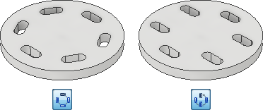
- Off angle boundary planes, not parallel to the feature normal, can result in differing results as illustrated in the following image.
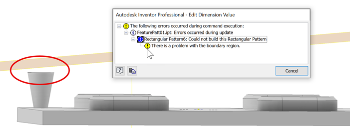
- If a boundary plane is created or edited such that the plane does not intersect the feature being patterned, this creates an error condition and a message displays. The geometry must intersect the boundary plane.
Pattern Part Features or Bodies on Sketch Points
The Sketch Driven Pattern command arranges occurrences of a feature or body on 2D or 3D sketch points. It duplicates one or more features or bodies and arranges the resulting occurrences in a pattern defined by the sketch points.
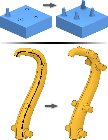
Create sketch points in a 2D or 3D sketch on your model and arrange them in the required pattern.
Click 3D Model tab
Pattern panel Sketch Driven  .
.In the tools palette, specify what you want to pattern:
- Patterns a solid body, including features that you cannot pattern individually. Can also include work features and surface features. Not available in an assembly.
- Patterns individual solid features, work features, and surface features. Cannot pattern assembly work features.
In the property panel, the geometry selector is immediately active. You can begin selecting one or more features or bodies to include in the pattern. For parts, you can also select work features and surface features to include in the pattern.
If there is more than one sketch or the sketch is invisible, select the sketch to use.
Specify the placement:
Sketch Point Select a 2D or 3D sketch to get all center points.
Base Point Select a vertex or point to change the occurrence origin.
Orientation: Specify the orientation of the pattern.
- Fixed Select if you want the orientation of the body or feature set to be identical to the parent selection as it is created along sketch.
- Follow Face Select if you want the body or feature set to follow face.
If patterning a solid, choose an operation:
- Join Attaches the pattern to the selected solid body. Patterns the solid as a single, unified body.
- New Solid Creates a pattern consisting of multiple individual solid bodies.
Set the creation method of the patterned features:
- Optimized. Creates identical copies of selected features by patterning feature faces. Optimized is the fastest compute method. Limitations are the inability to create overlapping occurrences, or occurrences that intersect different faces than the faces of the original features. When possible, speeds up the pattern compute.
- Identical. Creates identical copies of selected features by replicating the results of original features. Use for identical features when the Optimized method is not possible.
- Adjust. Creates potentially differing copies of selected features by patterning features and calculating extents or terminations of each pattern occurrence individually. Computation time is lengthy for patterns with large numbers of occurrences. Preserves design intent by allowing pattern occurrences to adjust based on feature extent or termination conditions, such as a feature that terminates on a model face. Not available for patterns of solid part bodies in an open or surface state.
Click OK.
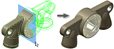
Arrange Part Features or Bodies in a Mirror Pattern
The Mirror command makes a reverse copy of one or more features, an entire solid, or a new body at equal distances across a plane. Use a workplane an existing planar face for the mirror plane.
Do one of the following:
- In a part file, click 3D Model tab Pattern panel Mirror
 .
. - In an assembly file, click Assemble tab Pattern panel Mirror
 .
.
- In a part file, click 3D Model tab
In the Mirror dialog box, specify what you want to mirror:
Mirror Individual Features
 . Selects solid features, work features, and surface features to mirror. If selected features have dependent features, they are automatically selected. In assemblies, you can mirror only sketched features. You cannot mirror:
- assembly work features.
- single sheet metal flange and contour flange features defined using multiple edges.
- features that operate on the entire body (all fillets, all rounds, shell).
- features based on the results of an intersect operation.
Mirror a Solid
 . Selects part bodies. Allows you to optionally include work and surface features in the selection.
In the graphics window or in the browser, select the feature or features to mirror.
In the Mirror dialog box, click Mirror Plane and then select a workplane or planar face to use as the mirror plane. Use Mirror Component on the Assemble tab.
In a multibody part, select Solid and then choose the solid body to receive the mirror feature.
If mirroring a solid, choose an operation and decide if you want to remove the original:
- Join . Joins the feature to the selected body.
- New Solid
 . Creates a body in a multibody part.
 - Remove Original. Removes the original body. Only the mirrored occurrence remains in the part file. Use to model a left and right version of a part.
- Join
Click More
 to specify how mirrored features are calculated:
- Optimized. Creates identical copies of selected features by mirroring feature faces. Optimized is the fastest compute method. But it presents some limitations, such as the inability to create overlapping occurrences, or occurrences that intersect different faces than the faces of the original features. Speeds up mirror compute.
- Identical. Creates identical copies of selected features by replicating the results of original features. When the optimized method is not possible, use Identical for identical features. Calculates faster than the Adjust method.
- Adjust. Creates potentially differing copies of selected features by mirroring features and calculating extents or terminations of each mirror occurrence individually. Computation time can be lengthy for patterns with large numbers of occurrences. Preserves design intent by allowing mirror occurrences to adjust based on feature extent or termination conditions, such as a mirrored feature that terminates on a model face. Not available for mirrors of solid part bodies in an open or surface state.
Click OK.
Control Visibility of Features in Patterns
Temporarily suppress the display of work, solid, or surface features in a pattern. Features remain suppressed until you restore them.
Do any of the following:
To suppress or restore visibility of all occurrences of solid features in a pattern, select the pattern icon in the browser, right-click, and choose Suppress or Unsuppress Features.
To suppress or restore visibility of an individual occurrence of a solid feature in a pattern, expand the pattern icon in the browser, select the occurrence, right-click, and choose Suppress, or Unsuppress.
Note: Note: Occurrences that are suppressed individually must be restored individually.To hide or restore visibility of all work features or surface features in all pattern occurrences, select the pattern icon in the browser, right-click, and choose Hide All Work Features, Show All Work Features, Hide All Surfaces, or Show All Surfaces.
To hide or restore visibility of an individual work or surface feature in a pattern occurrence, expand the pattern icon in the browser, select the occurrence, right-click, and then switch on or off the Visibility option.
Control Opacity of Surface Features in Patterns
When you create a surface, it is transparent and is the same color as a workplane. Use the Transparency option to make surfaces opaque.
Do either of the following:
- To control opacity of all surface features in all pattern occurrences, select the pattern icon in the browser, right-click, and choose All Surfaces Opaque or All Surfaces Transparent.
- To control opacity of an individual feature in a pattern occurrence, expand the pattern icon in the browser, then expand the occurrence icon. Select the feature, right-click, and switch on or off the Transparent option.
Editing a Pattern Feature
- In the graphics window or the browser, right-click the feature and choose Edit Feature. The feature dialog box displays.
- Change the pattern type, number, direction, or spacing.
- Click OK.
The Hole feature is a special case. Holes with a Termination of Through All pattern the portion of the solid that is penetrated by the initial feature. If the result is not what you want, change the termination to Distance.