To Create and Edit Sketch Patterns
Use the Pattern commands to create patterns of sketch geometry with or without a bounded area. Sketch geometry outside the boundary criteria displays in a different color and line style for ease of identification. Patterned geometry is fully constrained, and the constraints are maintained as a group. If you remove the pattern constraint, all constraints to the pattern geometry are deleted.
If you remove the associative relationship among pattern elements, the geometry is no longer a pattern, but geometric elements that you can edit individually.
Create Rectangular Patterns (2D Sketches)
In a sketch, click Sketch tab
 Pattern panel, click Rectangular
  .
.The Rectangular Pattern dialog box opens and Select mode is active by default.
In the canvas, select the geometry to pattern.
In the Rectangular Pattern dialog box, click the selection tool under Direction 1 and then select geometry to define the first direction for the pattern. In the canvas, an arrow indicates the direction.
For Direction 1, enter how many elements to create in the Count field
 and how far apart they should be in the Spacing field
  Note: Spacing can be a parametric equation.
Repeat steps 3 and 4 for Direction 2.
(Optional) In the Extents section, click Boundary
 and in the canvas click inside the boundary you defined. The boundary is a sketch either drawn or projected. Specify the inclusion method for the bounded pattern. Choose from:
 Include Geometry, all pattern occurrences completely inside the boundary are used for the pattern.
 Include Centroids, all pattern occurrences with centroids within the boundary are used for the pattern.
 Base Points, click the base point selector
  and select a base point on an occurrence, then all occurrences with base points inside the boundary are used for the pattern. To redefine the base point, click the selector and then select a different point as base point. Note, the selection updates when the new point is selected.
(Optional) Expand
 the dialog box and select advanced options:
- Suppress. Suppresses the elements you select. Suppressed elements are not included in profiles or drawing sketches. In features that consume the geometry, you must suppress elements manually. Suppressed elements appear in dashed lines in the canvas.
- Associative. If selected, the pattern updates when changes are made to the part. If deselected, removes constraints and the pattern does not update when you change an element.
- Fitted. Specifies whether pattern elements are equally fitted within the specified distances. If deselected, the pattern spacing measures the distance between elements instead of the overall distance for the pattern.
Click OK to create the pattern.
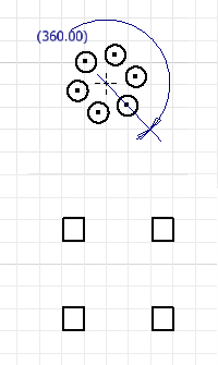
Create Circular Patterns (2D Sketches)
In a sketch, click Sketch tab
Pattern panel, click Circular  .
.The Circular Pattern dialog box opens and Select mode is active by default.
In the canvas, select the geometry to pattern.
In the Circular Pattern dialog box, click the Axis selector and then select a point, vertex, or work axis to define as the pattern axis. In the canvas, an arrow indicates the axis.
Enter how many elements to create in the Count field
 and the number of degrees between the first and last pattern elements in the Angle field
  .Note: Angle can be a parametric equation.
(Optional) In the Extents section, click Boundary
and in the canvas click inside the boundary you defined. The boundary is a sketch either drawn or projected. Specify the inclusion method for the bounded pattern. Choose from:- Include Geometry, all pattern occurrences completely inside the boundary are used for the pattern.
- Include Centroids, all pattern occurrences with centroids within the boundary are used for the pattern.
- Base Points, click the base point selector and select a base point on an occurrence, then all occurrences with base points inside the boundary are used for the pattern. To redefine the base point, click the selector and then select a different point as base point. Note, the selection updates when the new point is selected.
(Optional) Expand
the dialog box and select advanced options:- Suppress. Suppresses the elements you select. Suppressed elements are not included in profiles or drawing sketches. In features that consume the geometry, you must suppress elements manually. Suppressed elements appear in dashed lines in the canvas.
- Associative. If selected, the pattern updates when changes are made to the part. If deselected, removes constraints and the pattern does not update when you change an element.
- Fitted. Specifies whether pattern elements are equally fitted within the specified angle. If deselected, the pattern spacing measures the angle between elements instead of the overall angle for the pattern.
Click OK to create the pattern.
Edit Rectangular and Circular Patterns
Do any of the following:
- Right-click a pattern element in the canvas and choose Edit Pattern. Change any values in the Rectangular Pattern or Circular Pattern dialog box and click OK.
- Double-click a pattern dimension in the canvas to change it.
- Select a pattern or pattern element in the canvas, right-click and choose any of the following, depending on what’s selected:
- Delete. Removes nonpattern geometry from the sketch.
- Delete Pattern. Removes the entire pattern from the sketch.
- Suppress Element(s). Makes the element(s) unavailable in the sketch. Preserves relationships among remaining pattern elements. Suppressed elements appear in dashed lines in the canvas.
Create Mirror Patterns
In a sketch, click Sketch tab
Pattern panel Mirror  (2D) or 3D Sketch tab Pattern panel Mirror (3D)
The Mirror Pattern dialog box opens and Select mode is active by default.
In the canvas, select the geometry to pattern.
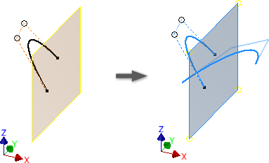
In the Mirror Pattern dialog box, click the selection tool under Mirror Line (2D) or Mirror Plane (3D) and then select a line or plane to about which to mirror the geometry.
In the canvas, a blue arrow indicates the line or plane.
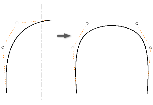
(Optional, 2D) If you’re mirroring a spline that intersects with the mirror line, select Self Symmetric to create a single spline that is symmetric about the mirror line.
Click Apply to finish the pattern and create more or click Done to create the pattern and exit the command.