To Modify or Apply End Treatments to Frames
What's New: 2021
Start in the assembly environment with an assembly model open.
Miter
Miter the ends of frame members.
 On the ribbon, click Design tab
  Frame panel Miter.
Do one of the following:
- Select a single pair of frame members to miter.
- Select multiple frame members to miter.
Optionally, select a saved Preset to configure the miter.
To replace an existing end treatment with the miter, click the Advanced Settings Menu and select Delete existing end treatments. Clear the selection if it is not necessary to delete an existing end treatment.
Select a miter type:
 Full Miter Cut
 Bisect Miter Cut
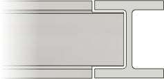
The following image displays the difference in miter cut types when applied to frame members of different sizes.

Select or enter a distance between the mitered cuts.
Select an offset type:
 Default
 Flipped
 Symmetric
Click Apply.
Continue to apply miters to frame members as needed. When you finish, click OK.
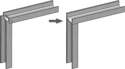
Corner Joint
Creates a corner joint by lengthening or shortening frame members.
 On the ribbon, click Design tab Frame panel Corner Joint.
 Optionally, Select a saved Preset
 To replace an existing end treatment with the operation, click the Advanced Settings Menu and select Delete existing end treatments. Clear the selection if you do not want to delete an existing end treatment.
 Click to select the first frame member to trim or extend.
 Click to select the second frame member to trim or extend.
The first selection is previewed in yellow, and the second selection is previewed in blue. The blue selection represents the member to be trimmed.
Note: You can continue to select and add frame members to the operation. If you select more than two participants, all selected members change to a blue preview and it becomes difficult to predict which members are trimmed or extended. Optionally, click Flip Members to reverse the selection. For example, if two members selected, the yellow selection is changed to blue and the blue selection is changed to yellow.
Optionally, enter a value for Offset1 and Offset 2.
Click Apply.
Continue to create corner joints as needed. When you finish, click OK.
Trim/Extend To Face
Trim or Extend a frame member to a model face.
 On the ribbon, click Design tab Frame panel Trim/Extend.
- Optionally, click the Advanced Settings Menu to set preferences.
 Select a model face to define the Tool for the cut or extend.
 Select the frame members to cut or lengthen.
 Optionally, click Flip face normal to reverse the side to receive the trim or extend as shown in the following image.
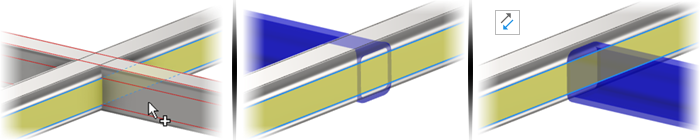
Select or enter the offset distance between the frame member and model face.
Click Apply to extend or trim the frame member to the model face you selected.
Continue to trim or extend frame members as needed, and then click OK.
The values generated by applying the Trim/Extend command to cut angles display in the iProperties/Custom tab as CUTDETAIL1, CUTDETAIL2, and so on, and can be included in the Bill of Materials and Parts List.
Update panel Rebuild All.Notch
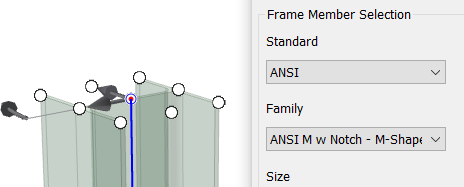
Trim and extend frame members at their ends to provide a notched fit using one of the following options:
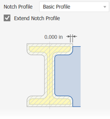
Basic Profile
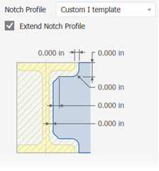
Custom I template
Custom C template
Custom T template
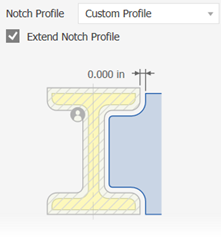
Custom Profile
Note: To use the Custom Profile option, author the notch shape in the Content Center, and then consume the member containing the custom notch profile in the assembly.
For more information, click the How to Create Custom Profile in the panel or see Author Frame Generator Notch End Treatments
 On the ribbon, click Design tab Frame panel Notch.
Optionally, select a saved Preset to configure the notch.
To replace an existing end treatment with the notch, click the Advanced Settings Menu and select Delete existing end treatments. Clear the selection if it is not necessary to delete an existing end treatment.
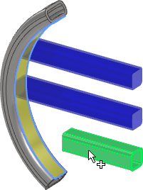
 Click to select the frame members to receive the notch.
 Click to select the frame members that represent the shape of the notch.
Choose one of the following:
Basic Profile to set a single offset value for the notch.
Custom I, Custom C, or Custom T template to set multiple offset values.
Custom Profile, if available, to use the custom notch profile in the Content Center family.
Optionally:
- Check Extend Notch Profile, if available, to extend the profile to an intersection.
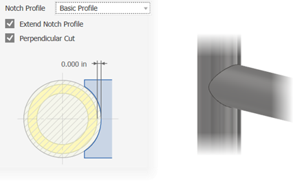
- Check Perpendicular Cut, if available, to create precise intersections such as a laser cut notch for a pipe.
Click Apply to notch the selected frame members.
Continue to notch frame members as needed. When you finish, click OK.
Lengthen/Shorten Frame Member
Extend or retract one or both frame member ends.
 On the ribbon, click Design tab Frame panel Lengthen/Shorten.
- Optionally, select a saved Preset.
- To replace an existing end treatment, click the Advanced Settings Menu and select Delete existing end treatments. Clear the selection if it is not necessary to delete an existing end treatment.
- Select the frame members to lengthen or shorten. Pick point a point on the frame member near the end to extend or retract.
- Select an offset type:
- Default
- Flipped
- Symmetric
 Asymmetric
- Enter a value for the offset between the frame member and the model face. A positive number extends, and a negative number retracts.
- Click Apply to extend or retract the frame members you selected.
- Continue to extend or retract members as needed. When you finish, click OK.
Remove End Treatments
Removes end treatments and returns the selected frame members to their original insertion state.
 On the ribbon, click the Design tab. Click the Frame panel drop-down arrow and select Remove End Treatments.
 Click to select the frame members from which to remove the end treatments.
- Click Apply to remove the end treatments from the selected frame members.
- Continue to remove end treatments as needed. When you finish, click OK.