To Create a Shell
What's New: 2026
You can create a shell with uniform or unique thickness.
The Draft feature applies a taper to part faces to cant a surface or allow a part to be extracted from a mold. Draft is defined by specified faces, pull direction, angle, and fixed edge or tangent surface. You can create three types of drafts in Inventor: Fixed Edge, Fixed Plane, or Parting Line.
To begin, create a 3D part with faces or edges to draft.
Key Concepts
- The Property Panel workflow is progressive and flows from top to bottom of the panel. Parameters in a section affect the feature and set the context for the following sections in the panel.
- Rename active shell from the property panel by clicking the breadcrumb text to select it, then clicking again to edit the text.
- Parameter values can be edited in the property panel, in-canvas, or by clicking-dragging the feature parameter manipulator. Active manipulators highlight in the canvas, and in the property panel the associated field has focus.
- Edited values in the property panel can be committed by pressing Enter or Tab to move to the next field. Press Ctrl+Enter to create the shell and close the property panel.
- Reference dimensions, non-editable, are displayed inside parentheses.
- Preview controls
 are provided during both feature and sketch editing.
 - The property panel experience is the same whether working in a part or assembly model.
- Use predefined shell preset if desired.
Create a Shell
The Shell feature removes material from a part interior, creating a hollow cavity with walls of a specified thickness. Selected faces can be removed to form a shell opening.
Click 3D Model tab
 Modify panel Shell
  .
.Specify the shell type:
 Sharp Corners. Creates sharp offset corners.
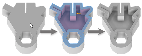
 Rounded Corners. Adds rounds to feature generated corners. Use this type to create a full or partial result that you can modify with surface tools.
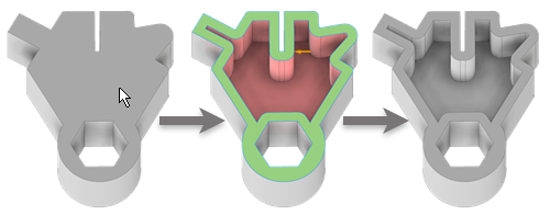
Specify the direction of the shell boundary relative to the part face:
 Inside. Offsets the shell wall to the part interior. The external wall of the original part becomes the external wall of the shell.
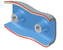
 Outside. Offsets the shell wall to the exterior of the part. The external wall of the original part is the internal wall of the shell.
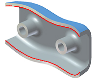
 Center. Offsets the shell wall equal distances to the inside and outside the part. Adds half of the shell thickness to the thickness of the part.
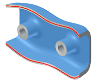
Specify the shell’s Thickness.
Thickness is applied uniformly to shell walls. To use the thickness value in a parameter table, highlight the value in the box, and then right-click to cut, copy, paste, or delete it.
(Optional)
 Remove faces where the shell won't be created.
In the Advanced Properties section, specify whether and how to calculate approximations:
- Allow Approximation. When no precise solution exists, allows a deviation from the specified thickness while computing the offset feature. A precise solution creates an offset surface where each point on the original surface has a corresponding point on the offset surface. The distance between these two points is the specified distance.
- Mean. If approximation is allowed, deviation is divided to fall both above and below the specified distance.
- Never Too Thin. If approximation is allowed, preserves minimum distance. The deviation must fall above the specified distance.
- Never Too Thick. If approximation is allowed, preserves maximum distance. The deviation must fall below the specified distance.
- Tolerance as Optimized. Computes approximation using a reasonable tolerance and minimal compute time.
- Tolerance as Specified. Computes approximation using the tolerance you specify. Valid tolerance range is from 0-100. Considerable compute time may be required.
Click OK.
If an approximation is used, click OK in the message box to accept the results or Edit to return to the Shell property panel.