To Create, Lock Spline Length, and Edit Splines
2D and 3D splines are curves of constantly changing radius. Inventor supports two types of splines: interpolation splines and control vertex splines. Interpolation splines can be created in both 2D and 3D sketches and on a surface.
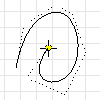
Interpolation splines pass through a series of points, called fit points. You modify the curve using handles on the points. In the graphics window, interpolation spline endpoints are square and fit points along the curve are diamond shaped.
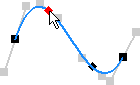
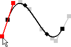
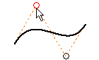
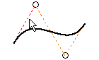
Control vertex splines are defined by a control frame. When you create the spline, the control frame displays as construction lines. Control vertices on the frame, which display as circles, influence the spline curves. The spline is tangent to the control frame at the start and end points.
You can partially or fully constrain spline points. Infer constraints to existing geometry as you draw the curve, or add constraints and dimensions later.
Create Interpolation Splines
- In an active sketch, click Sketch tab
 Create panel > Interpolation Spline
  (2D) or 3D Sketch tab Draw panel Interpolation Spline (3D sketch).
 - In the graphics window, click to set the first point, or click an existing point.
- Continue clicking to create fit points. To close a loop, right-click the starting point and choose Close Curve.
Create Control Vertex Splines
- In an active sketch, clickSketch tab Create panel Control Vertex Spline
 (2D) or 3D Sketch tab Draw panel Control Vertex Spline (3D sketch).
 - In the graphics window, click to set the first point, or select an existing point.
- Continue clicking to create vertices.
- When you’re done, click OK to finish the spline and exit the command or click Apply to finish the spline and create more.
Change Spline Type
Right-click an interpolation spline and choose Convert to CV Spline.
Right-click a control vertex spline and choose Convert to Interpolation.
Note: If you convert a spline and then convert it back, the spline doesn’t have the same fit points or control frame as the original. The initial conversion creates a best-fit spline and adds more points or vertices.
Lock Spline Length
When you add a general dimension to an interpolation spline, a length dimension is added which prevents the overall length of spline from changing. As components move or shift, although the shape continues to adjust, the total spline length remains the same.
- On the ribbon 3D sketch tab Constraints panel General Dimension
 .
. - Select the interpolation spline geometry to dimension.
Edit Interpolation Splines
Do any of the following:
Drag a point to reposition it; drag an end point to resize the shape.
Drag the spline to move or reposition it.
To edit the shape of the curve, right-click a tangent handle and choose Activate Handle. Then, drag the tangent handle to adjust the spline shape.
To delete a spline, select it and press Delete.
To add a point, right-click the spline and choose Insert Point. Then click the curve to add one or more points. Press Esc when you’re done.
To close a curve, right-click the starting point and choose Close Curve.
To delete a point, select it and press Delete.
Tip: To delete the spline but preserve the fit points, convert the points to center points, then select the spline and press Delete.To split a spline, right-click a point and choose Split Spline.
To reverse an edit, right-click the spline and choose Reset Handle or Reset All Handles.
To change the fit method, right-click a spline choose one of the following:
- Standard. Creates curves with smooth continuity between points.
- Minimum Energy. Creates smooth curves with high visual appeal and better curvature distribution. Because Minimum Energy splines contain more data, surfaces generated using them take longer to calculate and create larger files.
- AutoCAD. Uses the AutoCAD spline-fitting method. Interpolation splines that use the AutoCAD fit method do not have handles and are not suitable for creating class A surfaces.
To adjust spline tension, right-click the spline and choose Spline Tension. Drag the slider toward 100 to tighten the curve; drag toward 0 to make it loose (more open). Click
 when you’re done. Adjusting spline tension automatically converts that spline to the Minimum Energy fit method.
Edit Control Vertex Splines
Do any of the following:
Drag a control vertex to reposition it. Drag an end point to resize the shape.
Drag the control frame to change the spline shape.
Drag the spline to move it.
To delete a spline, select it and press Delete.
To add a vertex to the control frame, right-click the spline and choose Insert Vertex. Then click the frame to add one or more vertices. Press Esc when you’re done.
To delete a vertex, select it and press Delete.
Note: You can delete control points only if the spline has four or more, including the start and end points.To turn visibility of the control frame on and off, right-click it and choose Polygon Visibility.
 Show Me How to Create Control Vertex Splines
Visualize Spline Curvature
Curvature is a mathematical indication of the smoothness between curves or surfaces. The rate of change of direction is called curvature. You can visualize spline curvature and overall smoothness in Inventor by displaying the curvature comb.
The comb illustrates curvature with a series of connected spines that radiate outward from the curve. Longer spines indicate areas of higher curvature, and shorter spines indicate lower curvature. The length of each spine is equal to the curvature of the spline at that point, adjusted for the view scale. The progression of the tips of the spines indicates how continuous and smooth the curvature of the spline is.
- To view spline curvature, right-click a spline and choose Display Curvature.
- To adjust the display of comb, right-click a spline and choose Setup Curvature Display.
- Comb Density
 . Specifies the spacing between spines.
 - Comb Scale
 . Specifies the scale (length) of the spines.
- Comb Density