To Import IFC data as an AnyCAD Model
Learn about the different ways for importing IFC data into your Inventor designs.
What's New: 2025, 2025.2, 2026
Access
The points of access for importing the CAD files are:
- Home
 Open
Open - File Open Open
- File Open Import CAD Files
- Quick Access Toolbar (QAT) Open
- New Part Manage tab Insert panel Import
- Drag and drop the IFC file onto the Inventor window Title bar or into the canvas (graphics area).
- In an Assembly document, in the Assembly tab Components panel Place Imported CAD Files
You can add additional IFC content to an existing Inventor IFC model.
Importing IFC data
The workflow is similar whether creating new datasets from an IFC file or placing additional IFC content into a model with existing IFC content. There is a small difference:
- New model: In the QAT or on the Home tab, click Open. Or, use one of the other access points.
- Adding to an existing model: In the Assemble tab in the Component panel expand the Place drop down and click Place Imported CAD Files.
In the Open dialog,
- Set the Files of type to IFC Files (*.ifc; *.ifcXML; *.ifcZIP).
- Navigate to and select the IFC model you want to import.
- Click Open. This action is file size dependent, progress is displayed for longer times.
In the Import dialog box:
Options tab
Import Type
Select either Reference Model or Convert Model.
 Reference Model
- Retains associativity with the source IFC model. When the IFC model changes, the Inventor model receives a notification and you choose whether or not to update the model.
- Is Read-only. Changes to the source IFC model must be done in the application that authored the IFC file.
- With the imported model, you can:
- Constrain Inventor components to the geometry.
- Project geometry into other Inventor models.
- Hide components.
- Suppress or break the link between the source and reference files.
- Modify iProperties and copy AEC Properties.
- Override BOM fields.
 Convert Model
- Creates native Inventor files corresponding to the IFC elements. The files can be modified in any way or deleted.
- Does not retain associativity to the source data. Changes to the source IFC data are ignored.
Import Method
 Multibody: Imports IFC elements as individual bodies that are combined to create one model. Properties aren't imported. The bodies are placed in folders based on their IFC class.
 Assembly: Imports IFC elements as individual Inventor documents. Properties can be imported. For Reference models, the documents are maintained within the Assembly file and aren't otherwise accessible.
As Mesh: Select this option to import the IFC data explicitly as mesh objects. Otherwise, objects are imported according to the IFC data definition, as in solid, surface, or mesh. For a large dataset, mesh can expedite the import process.
Import Properties
As Parameters: Stores IFC properties as Inventor parameters and Instance Properties for each element. How some properties are accessed is different for reference and convert models.
- For Reference models, parameters and properties are accessed by right clicking the component browser node and, in the menu, click AEC Properties. Instance Properties are only available for the top level node in reference models.
- For Convert models, properties can be viewed by right-clicking the browser node and clicking AEC Properties. Use the Parameters
 command, iProperties, and Instance Properties to modify property values. Use the Instance Properties command to access element properties.
 - As Custom iProperties: This option marks the imported parameters for export as Custom iProperties. These properties are accessed in the iProperties dialog, on the Custom tab.
Note: Empty parameters, property folders, and fields in the IFC file, are not imported. If populated later, the Reference model will update with the changes.
Inventor Length Units
Specify the Document Units to use for the import. Unit types are: From Source, inch, foot, centimeter, millimeter, meter, micron.
Import Summary
- Choices made in the dialog sections display as icons in the summary.
For example: The following summary reports the selected options for the active import as: 1) converted, 2) as an assembly with components, 3) with IFC parameters, 4) that are marked for export and show up as custom iProperties. If the import is mesh, an additional icon displays.
- After loading the model, Elements included displays the number of elements that will be imported as Inventor parts.
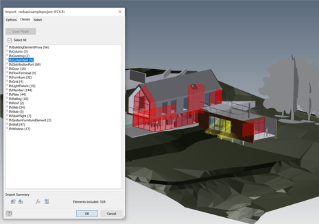
Classes tab
The Classes tab lets you use IFC classifications to manage what is included or excluded from the import.
Click Load Model to see a model preview in the canvas (graphics area). An alphabetically sorted list of IFC Classes to be imported displays.
All classes are selected by default. Deselecting a class excludes all elements in that class from import. The element count updates as you deselect classes.
 Tip: Use this option to remove all elements in unnecessary classes.
Select tab
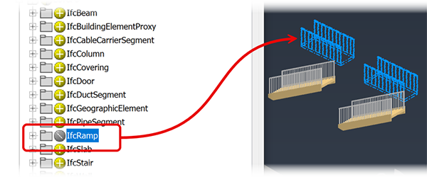
The Load Model option is available here also. The elements display hierarchically with an Include
 icon indicating the elements are included in the Import. Clicking an icon changes the state from Include to Exclude
  . All elements contained in that assembly, folder, or element are excluded from the import. This enables you to import only the elements you want in any class. Click the icon again to revert the exclusion.Tip: Combining the capabilities of the Classes and Select tabs makes it possible to create the exact import needed for your design. Classes are good for bulk removal of geometry that is unnecessary and the Select tab helps to fine tune the import result.
The following example shows a set of ramps being excluded.
Click OK. The file is imported as a subassembly. You can place one or more instances of the model in the Inventor assembly
Note: If an error occurs with the import, the translation log displays explaining the issue encountered.
AEC Properties
These are IFC properties that are imported as AEC Properties, if you select the As Parameters option. The properties:
- Are read-only
- Viewed using the AEC Property panel.
- Values can be copied and pasted where needed.
- That use the same name as Inventor properties, have an "IFC_" prefix to clarify which is the IFC property.
- Update with changes to the IFC file. Changes are made in the IFC authoring application.
To access the AEC Properties do the following:
- In Assemblies, go the the Inspect tab, and select AEC Properties in the Properties panel.
- In the model browser, expand the imported model node to locate the element whose properties you want to see or use the browser search.
- Right-click the browser node and at the lower end of the context menu, click AEC Properties.
- Alternatively, set the selection options to Select Part Priority and, in the canvas, select a part.
Updating Reference Models
The update notification, lightning bolt next to a browser node, appears when:
- the source IFC data is modified
- Inventor components used in the assembly are modified
When the lightning bolt displays, click the Local Update command to apply all pending changes, this includes both the IFC data and Inventor components. Updates may affect dependencies, such as constraints and adaptive parts.
Editing the Reference Model Import
Any time after the import is completed, you can edit the import.
In the Model Browser, right-click the IFC model node and choose the action to perform, use:
- Edit Import to display the Import panel and modify options, access the Classes or Selection tabs and alter selected content.
- Suppress Link to suspend updates from the source model. To resume updates, right-click the import browser node and click Unsuppress Link.
- Break Link to terminate the link to the source model. Internal files are saved as external files, thereby making the import the same as if you had used the Convert option. The model is no longer linked to the source and updates from the source no longer occur.