To Create a Sheet Metal Contour Flange
You can create a contour flange, specify its dimensions, and create a multi-edge contour flange with auto-miter.
What's New: 2026
This command uses a property panel interface for both creating and editing the feature.
Property panels provide an enhanced workflow and eliminate the tabbed interface. Certain controls are common to all property panels. For details about common controls, see About Property Panels.
Presets are pre-existing parameter sets that are applied to the feature when selected. Presets are used for most property panel-based commands. For more information, see. To Work with Presets.
As you interact with the property panel, the selected row highlights in order to confirm where you are editing. The highlight is controlled by the Color Scheme Application Options settings. You can modify the settings to manage your color preferences.
Note: Color Scheme modifications are applicable across all of Inventor.The property panel displays only those parameters that are needed for the conditions you choose. When the flange is the base feature, only certain parameters display. When the flange is an additional feature, the options display based on the choices you make as you proceed down the property panel.
- Hover the cursor over any input field to see the parameter and its value.
Create a base feature contour flange
On the ribbon, click Sheet Metal tab
 Create panel Flange
  .
.(Optional) Use a preset that you have created from a previous contour flange feature.
In the Input Geometry group, do the following:
- Profiles. If a valid open profile exists it is automatically selected. If more than one option exists, select an open profile. If no profile exists you are placed in the Sketch Environment to create a profile.
- Body Name. Displays only when New Solid is used. Accept the default naming or specify a name.
- SM Rule. Select the sheet metal rule to use.
The Feature Placement group displays only when the selected IDE file has a dependency on geometry references for placement, such as an edge or face. Select the required placement geometry and continue defining the flange parameters.
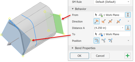
In the Behavior group, specify the following parameters as needed:
From. By default, uses the profile sketch plane.
Between. Specify a different From and To terminations. Valid inputs are face, point, or work feature.
 Note: When using Between, Direction and Distance are reference values defined by the From and To selections.
Direction. Specify the flange direction choosing from:
 Default
 Flipped
 Symmetric
 Asymmetric
Distance A. Specify the length of the contour flange.
Distance B. Displays when a second distance value is required. Specify the distance.
 To. Pick a work feature or planar face as the flange termination. Distance is a reference value when To is used.
Position. Specify the side of the profile where the flange is created.
 Default uses the profile as an interior edge.
 Flipped uses the profile as an exterior edge.
 Symmetric specifies an equidistant offset from the profile.
In the Bend Properties group, you specify the Bend Radius and Unfold Rule to use.
Click OK to end flange creation, or
 Apply to continue adding contour flanges.
Create a contour flange on an existing solid
You can add a contour flange to an existing sheet metal face. Create the sketch profile on a face perpendicular to the edge for the contour flange.
On the ribbon, click Sheet Metal tab
Create panel Flange .In the Input Geometry group, do the following:
Profiles. Select an open profile if not automatically selected.
(Optional)
 New Solid. Select if the contour flange is to be a new body, separate from the selected solid.
- Body Name. Displays only when New Solid is used. Accept the default naming or specify a name.
SM Rule. Uses the active Sheet Metal Style Rule. If New Solid is selected, select the sheet metal rule to use.
In the Behavior group specify the following parameters:
Width Extents
 Along selected edge. Select this option to add a contour flange along selected edges.
Edge Sets are a collection of edges where the contour flange is added. Edge options are defined per Edge Set.
 Edge Loop sets the selection priority to edge loops. Select an edge and all contiguous edges are also selected.
 Add an Edge Set creates a new edge set entry. Select the edges to include in the set. This enables multiple flanges with varied width terminations to be defined.
For each edge set you can specify the method used for defining the flange.
- Edge uses the entire edge for the flange.
 Width. Specify the edge width. The flange is symmetrically placed from the edge center.
 Between. Use this option to create a flange between two elements. Elements can be points, workplanes, or faces.
 Offset Use this option to specify offset values for each side of the flange.
-  Use Clear selections to remove the select set.
From sketch plane. Specifies the contour flange will begin from the profile sketch plane.
From. Specifies the starting plane for the contour flange. By default, the profile sketch plane is selected. Disabled unless using Between.
 Between Use this option to specify a different start and termination location.
- From. Specify where the flange starts.
- To. Select a feature where the flange ends.
Direction. Specify the flange direction choosing from:
- Default
- Flipped
- Symmetric
- Asymmetric
Distance A. Specify the length of the contour flange.
Bend Edges. Select additional edges where the flange is placed.
Position. Specify the side of the profile where the flange is created.
- Default uses the profile as an interior edge.
- Flipped uses the profile as an exterior edge.
- Symmetric specifies an equidistant offset from the profile.
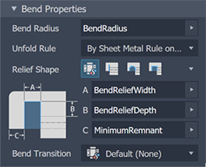
In the Bend Properties group use the rule defaults or specify the Bend Radius, Unfold Rule, Relief Shape, and Bend Transition you want to use. You can modify some parameters with explicit values or equations, or accept the default settings
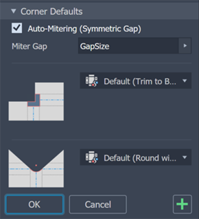
- In the Corner Defaults group use the rule defaults or set the Auto-mitering option, the Corner Shape, and Corner Relief. Select corner options from the corresponding list.
- In the canvas, for multi-edge flanges, you can specify individual corner parameters by means of Corner Overrides. Click a corner glyph to populate the corner in the property panel. Then, modify the corner settings for relief, shape, gap size, and relief size to fit your requirements.
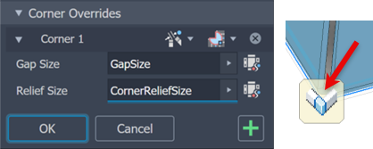
To enable gap and relief size fields, click the ![]() defaults icon next to the field.
defaults icon next to the field.
- To add more contour flanges, click Apply. If you are finished click OK.