The automation tool creates analytical elements for the selected structural physical objects. The created analytical model follows the engineering mind set through rule-based automation logic. The objects are aligned to project levels and grids, but also to calculated references.
The automation uses calculated defaults, but you can also adjust their settings using their parameters.
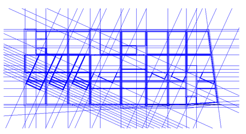
Align to Grids and Calculated In-Plan References
The selected structural physical model is analyzed by the automation tool to identify each dominant direction.
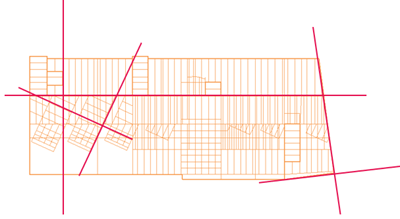
For each dominant direction, the selected structural elements are grouped based on their relative offsets.

For each identified group, a virtual grid is calculated. This virtual grid will be used as a vertical alignment reference to which all the elements in the group will be aligned in plane.

If a model grid is overlapping with this group, it will be considered the vertical reference to which all the elements of the group will be aligned in plane.
- In the Analyze tab
 Structural Analytical Model panel, click
 (Analytical Automation).
- From the drop-down list, select
 (Run Physical to Analytical for Buildings).
- In Modify | Modify, click
 (Align).
- From the drop-down list, select
 (Align: In Plan).
- In Modify | Align In Plan, adjust the tolerance as needed.
You can adjust this multiplication factor:
- In the Analyze tab Structural Analytical Model panel, click
(Analytical Automation).
- From the drop-down list, select
(Run Physical to Analytical for Buildings).
- In Modify | Modify, click
(Align).
- From the drop-down list, select
(Align: In Plan).
- In Modify | Align In Plan Mode, click
 (Preview Alignment) .
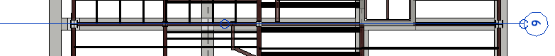
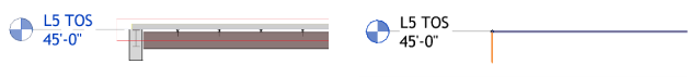
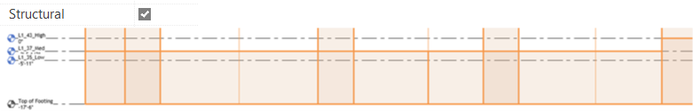
Align to Levels
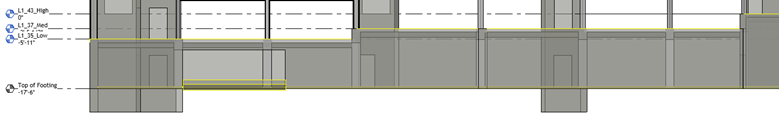
For the alignment on vertical, each model element is looking for a level within a tolerance. If a level is found within this tolerance, the analytical representation for this element is aligned to that level.
- For Beams it's their cross-section height.
- For Floors it's their thickness.
- For Columns and Walls it's their height.
- The beam geometrical axis.
- Floor and foundation slab top.
- Top or bottom of walls and columns.
This tolerance can be multiplied by a factor present in the automation tool settings for each type of object.
- In the Analyze tab Structural Analytical Model panel, click
(Analytical Automation).
- From the drop-down list, select
(Run Physical to Analytical for Buildings).
- In Modify | Modify, click
(Align).
- From the drop-down list, select
 (Align: To Levels).
- In Modify | Align To Levels Level Tolerances panel, adjust the tolerance values as needed.
If more levels are identified within the tolerance of the element, the level assigned to most of the elements will be the alignment level for all.
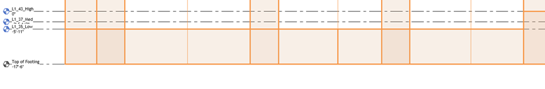
If you want to specify the level to which the elements will be aligned to, check the "Structural" parameter in the level properties.
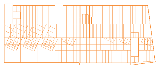
Align to Inclined Planes
The inclined planes are calculated virtual references, they are determined when the automation tool identifies a slanted rafter with an angle to the horizontal of less than 35 degrees.
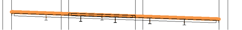
The analytical representation of this rafter and all the analytical elements that have physical counterparts in contact with this rafter, will be aligned to this plane.