Learn how to model a corner connection family for solid walls.
The geometry for corner connections is arbitrary, however, they must comply with several guidelines. This example is a metric family, but you can create Imperial versions similarly.
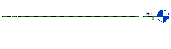
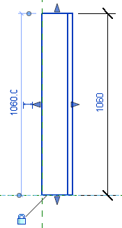
- In the Front Elevation, geometry must be sketched below the horizontal reference level and centered in relation to the vertical reference plane.
- When viewed from the top, geometry must be sketched to the right of the horizontal reference plane.
- A shared parameter, Instance Height, must be created to represent the height of the connection geometry in instances.
- In the Properties Palette, under Other, Cut with Voids When Loaded must be selected.
- Create a new family using a Metric Generic Model face based.rft template (metric or Imperial).
- In the Properties Palette, under Other, select Cut with Voids When Loaded.
- Open the Front Elevation view.
- Click Create tab
 Forms panel
 (Extrusion).
Note: The Create tab can only be accessed when working in the Family Editor.
(Extrusion).
Note: The Create tab can only be accessed when working in the Family Editor. - Click Modify | Create Extrusion panel Draw panel
 (Line).
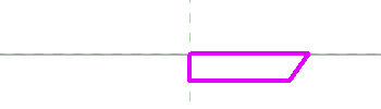
- Sketch the geometry for the corner connection below the horizontal reference level and to the right of the vertical reference plane.
- Click Modify tab Modify panel
 (Align).
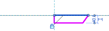
- Align and lock the top line of the geometry to the horizontal reference level.
- Align and lock the left line of the geometry to the vertical reference plane.
- Click Create tab Properties panel
 (Family Types).
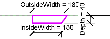
- Add the following type properties with appropriate values in the Family Types dialog.
- Depth
- Width Inside
- Width Outside
- Click OK to close the Family Types dialog.
- Click Annotate tab Dimension panel
 (Aligned).
- Place dimensions for the 3 type parameters.
- Select and specify the correct label for each dimension.
- Click Modify | Create Void Extrusion tab Mode panel
 (Finish).
- Open the Ref. Level Floor Plan view.
- Select the extrusion and using the shape handle, drag the top edge above the horizontal reference plane to about twice its height.
- Drag the bottom edge to snap to the horizontal reference plane and then lock it.
- Click Create tab Properties panel
(Family Types).
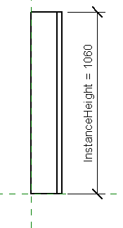
- Create a shared parameter named Instance Height and assign an appropriate value to it.
- Click OK to close the Family Types dialog.
- Click Annotate tab Dimension panel
(Aligned).
- Place a dimension for the height of the connection geometry.
- Select the dimension and label it as Instance Height.
- Click Create tab Properties panel
(Family Types).
- Create family types for the corner connection.
- Click OK to close the Family Types dialog.
- Save the family.
The corner connection family is ready to save and load into your project.