Exercise 16
Previous: Chapter 22 | Next: Exercise 17
This exercise teaches how to leverage an existing analysis to quickly and easily explore changes in your design.
Right click on the Baseline design in the Design Study Bar and select Clone…
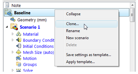
Enter the name “Floor Registers Active” to the cloned design. Click OK.
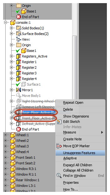
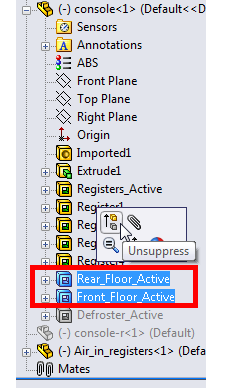
In the CAD model, enable the features that allow air to flow to the front floor and the rear floor registers. In the console part, activate the following features:
Rear_Floor_Active
Front_Floor_Active
Autodesk® Inventor*:
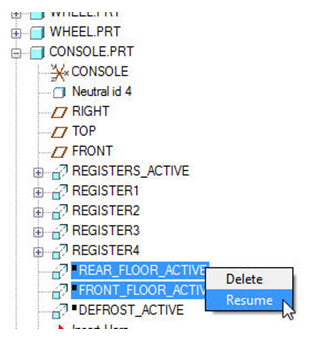
PTC Creo or Pro/Engineer:*
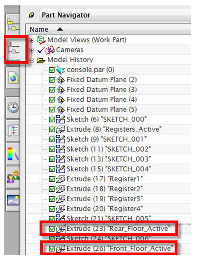
UG NX*:
Make console part (or console-r part) the working part and activate the part navigator. Check the box to enable each feature.
SolidWorks*:
 Note: The objective of this design change is to eliminate the higher floor temperatures. We hope to do this by adding registers to provide cold air to the front and rear floor regions.
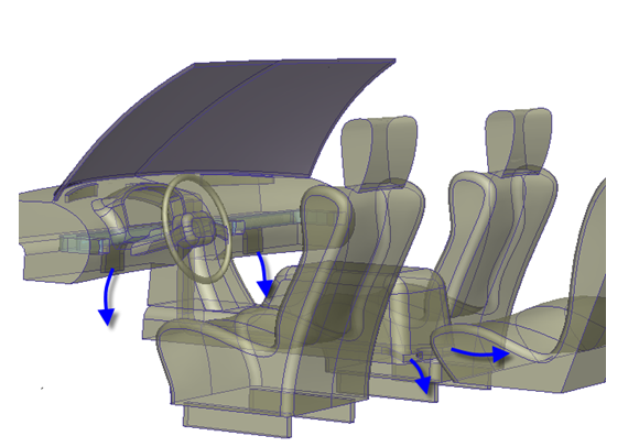
Launch Autodesk® CFD and update the cloned design with the new CAD geometry:
To launch from CAD
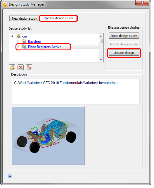
In the Design Study Manager, click the Update design study tab.
Expand the car design study.
Select the Floor Registers Active design.
Click Update Design.
In the Design Study Bar, note that there is a lost Air material setting. Right click on it and click Delete.
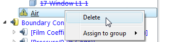 Note: Why? In the Baseline configuration, Autodesk® CFD generated three distinct air volumes (primary cabin volume, inlet, and an isolated volume in the console). When we added the rear floor registers, the third isolated region became part of the main cabin, and the Air material assigned to that part could not be assigned. It is therefore considered "lost," and has to be deleted before we can run this design.
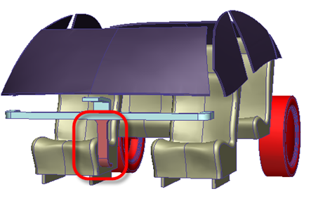 Important: Before proceeding, you should check the settings of the model to ensure that they are assigned in the correct locations. You should inspect the material and boundary condition assignments, in particular, and fix any settings that are not assigned to the correct part or surface.
Right click off the model and choose Solve…
Set Continue From to 0 and click Solve.
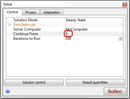
When prompted if you want to delete all results after iteration 0 and continue, click Yes.
Note: The simulation should take approximately 20 minutes to complete, but your time may vary, depending upon your computer.Note: At the conclusion of the simulation, the Convergence Plot closes, and the following appears in the Message Window: “Analysis completed successfully."