Chapter 6: The User Interface
Previous: Chapter 5 | Next: Exercise 1
In this chapter we learn about the main components of the user interface and the basics of working with Autodesk® CFD.
A Tour of the Autodesk® CFD User Interface
This is the default layout of the Autodesk® CFD User Interface:
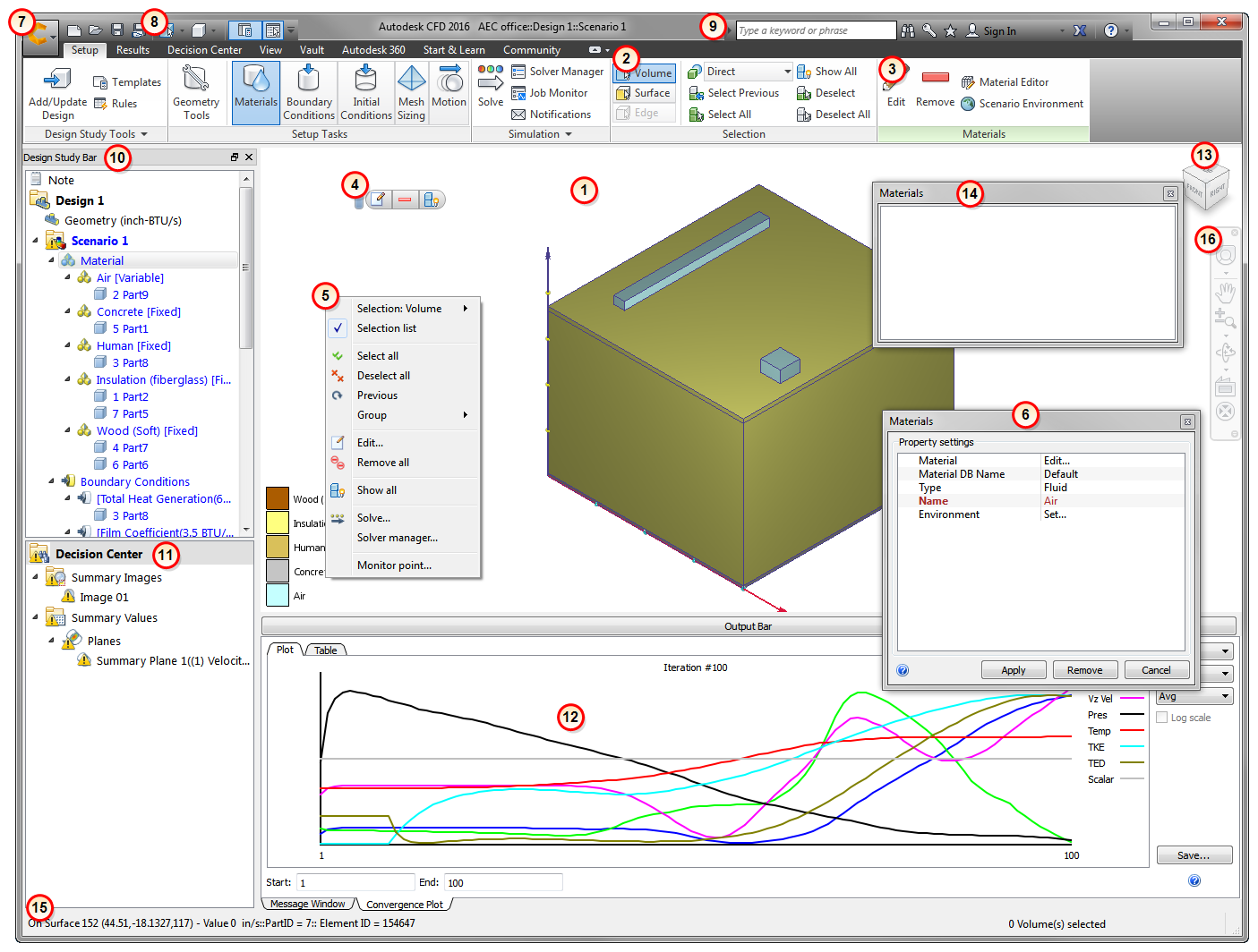
1. Graphics Window: View the model
The background color in the Autodesk® CFD Graphics window is set by the background color in the CAD tool.
To override this, open the Application menu, click Options, and change the setting for Background color to User defined.
2. Ribbon: Basics
The Ribbon is located across the top edge of the User Interface. Use them to interact with the model at all stages of the simulation.
Organization and Naming Convention
Each ribbon follows a simple hierarchal structure:
- Tab: The top-level organization level of the ribbon. All commands in a tab share a common purpose, and either support a particular stage in the simulation process (Setup and Results) or help accomplish a specific objective (View and Get Started).
- Panel: Groups of closely related commands
- Command: Individual commands on the ribbon. Commands come in several forms including buttons and menus.
Throughout the Autodesk® CFD Help topics, procedures refer to specific commands from the ribbon. To ensure clarity, each reference consists of the tab name, followed by the panel name, followed by the command name (Tab > Panel > Command).
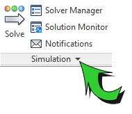
For example, this is the reference to the Solver Manager command in the Simulation panel of the Setup tab:
(Setup tab > Simulation panel > Solver Manager).
Drop-Down Menus
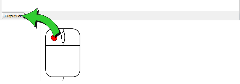
In the title bar of some panels, a small arrow indicates that additional controls are on a panel drop-down menu. To view these controls, click the arrow on the title bar of the panel:
By default, the menu disappears after the mouse if moved away. To lock the drop-down menu, click the pin icon:
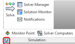
To hide the drop-down menu, click the pin icon again.
Customizing the Ribbon
The Ribbon appearance can be modified to suit individual preferences.
To change the location of a panel:
- Position the mouse over the panel title.
- Click and hold the left mouse button.
- Drag to the desired location.
To return a panel to its default location:
- Drag the panel to its position within the ribbon.
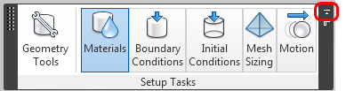
- Alternatively, hover the mouse over the panel until the border appears, and click the Return Panel to Ribbon icon:
To hide a panel:
- Right click on the panel title.
- Expand the Show Panels list.
- Uncheck the name of the panel.
To minimize the ribbon:
There are three ribbon minimization modes: tabls, panel titles, and panle buttons.
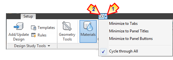
- To select the mode, click the menu arrow to the right of the tab labels (1), and select from the list.
- To minimize the ribbon to the selected mode, click the arrow button (2). To restore the ribbon to the standard configuration, click the arrow button again.
2. Ribbon: Tabs
There are four separate tabs in the ribbon. Each serves a specific purpose, and all are useful throughout the simulation process. Here is a brief description of the controls on each ribbon tab:
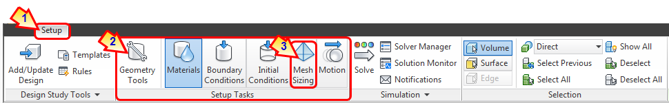
Setup
Use the Setup tab to define and run the simulation model:
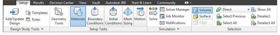
- Use Design Study Tools to update the Design Study and to manage Design Study Automation tools.
- Select each of the Setup Tasks, from left to right, to define the simulation. (Note that each task, except Geometry Tools, spawns an additional context panel.)
- Use Simulation to run and manage one or more simulations.
- Control entity selection with Selection.
Results
Use the Results tab to visualize and extract results data:
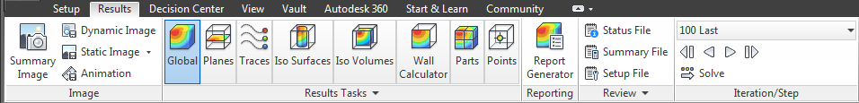
- Create and share images for design collaboration and design comparison using Image.
- Select the active results tool from Results Tasks. (Note that each task spawns an additional context panel.)
- Use Reporting commands to communicate your simulation results.
- Use Review to extract information about the current scenario.
- If the scenario has been continued multiple times or if intermediate iterations have been saved, select the iteration to view from Iteration/Step.
View
Use the View tab to control model appearance and to customize the User Interface:
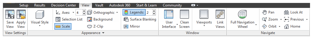
- Save a view and apply it to other models with View Settings.
- Control the display of model with Appearance.
- Configure the user interface and Graphics window with Windows.
- Control the model-position, -orientation, and -zoom with Navigate.
Vault
Use Vault to store and manage Autodesk® CFD data in the Autodesk Vault.
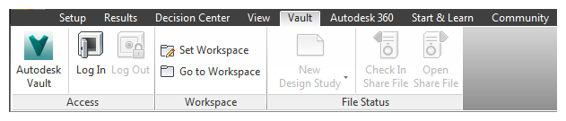
- Use Access to enter a Vault from Autodesk® CFD.
- Use Workspace to manage and access the local folder where data is stored when checked out from Vault.
- Use File Status to create and modify simulations using geometry stored in Vault. You can also check in and check out simulation files.
Autodesk 360
Use Autodesk 360 to sync Autodesk® CFD results images and setup files to your Autodesk 360 Documents folder.
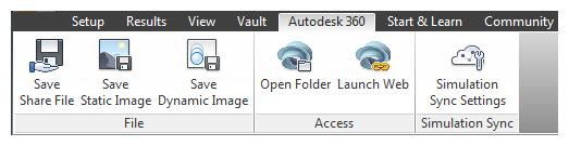
- Use the File commands to manually sync data to your Autodesk 360 account.
- Use the Access commands to manage your local cache and Autodesk 360 folders.
- Use Simulation Sync to configure how your simulation data is automatically uploaded to Autodesk 360.
Start & Learn
Use the Start & Learn tab to create or open a design study and to explore Help Resources:
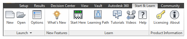
- Create or open a design study with Launch. (This is an alternative to launching from CAD.) Additionally, access Design Study Automation tools before opening a design study and prescribe user interface settings.
- Learn about new functionality with New Features.
- Explore Help and Learning resources with Learn.
- View product and licensing information with Product Information.
Community
Use the Community tab to Interact with other Autodesk® CFD users
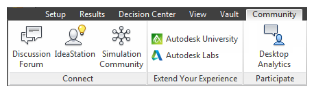
- Connect with other Autodesk® CFD users. You can share knowledge, collaborate with other users, and share your ideas for enhancement requests.
- Extend Your Experience to stay connected with the latest technology and innovation to come from Autodesk.
- Participate in the Desktop Analytics Program to influence the direction of Autodesk® CFD.
3. Context Panels
The controls in (Setup > Setup Tasks) and (Results > Results Tasks) invoke specific task modes that are the fundamental steps in the Autodesk® CFD process. Several commonly-used controls related to the active task are placed in an additional context-sensitive panel on the right side of the ribbon.
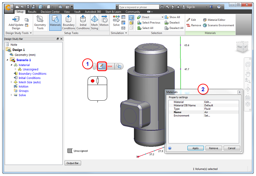
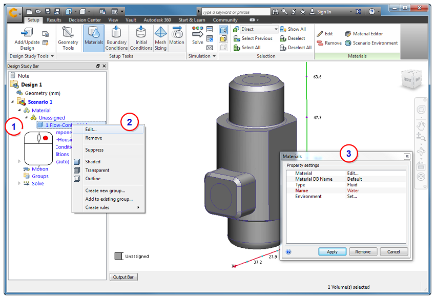
For example, when the Materials task is active on the Setup tab, the Materials context panel appears:

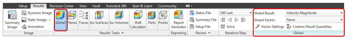
When the Global task is active on the Results tab, the Global context panel appears:
The active context panel is accessible when the View and Get Started tabs are selected as well. This provides uninterrupted access to essential controls after leaving the Setup or Results tabs.
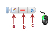
4. Context Toolbars
Context toolbars provide convenient access to frequently-used functions specific to the current task. To open a context toolbar, click the left mouse button.
Setup tasks (except Meshing)
- To assign or modify settings, click Edit (a).
- To deselect an entity, click Remove (b).
- To hide a selected entity or show all entities, click Hide or Show all (c).
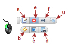
Meshing task
- To assign or modify settings, click Edit (a).
- To apply Automatic Sizing (b), construct Refinement Regions (c), run Diagnostics (d), and Suppress (e) or Resume (f) parts.
- To hide a selected entity or show all entities, click Hide or Show all (g).
For more about meshing...
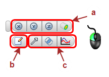
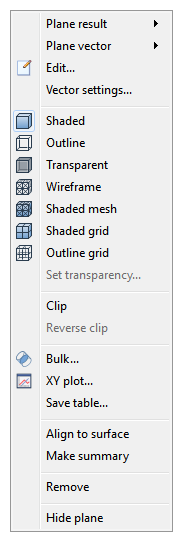
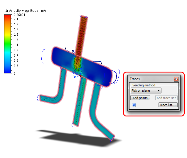
Plane task (in Results)
- Left click on the active result plane.
- Orient the plane (a).
- Modify appearance (b).
- Open Plane tools: Vector settings, XY Plot, Bulk (c).
For more about results planes...
5. Right-Click Menus
The right-click menus contain commonly used controls that are contextual to the current task. They provide convenient access to commands while allowing focus to be maintained directly on the model.
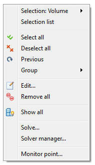
Setup Tasks
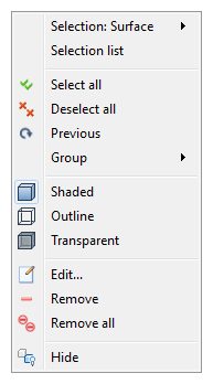
On every Setup task, use the right-click menus to change the selection type, select and deselect items, and open the appropriate Quick edit dialog. Additionally, access commands specific to the current task.
Right click off model:
Right click on part (Materials task):
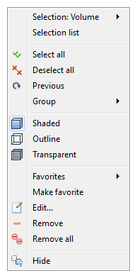
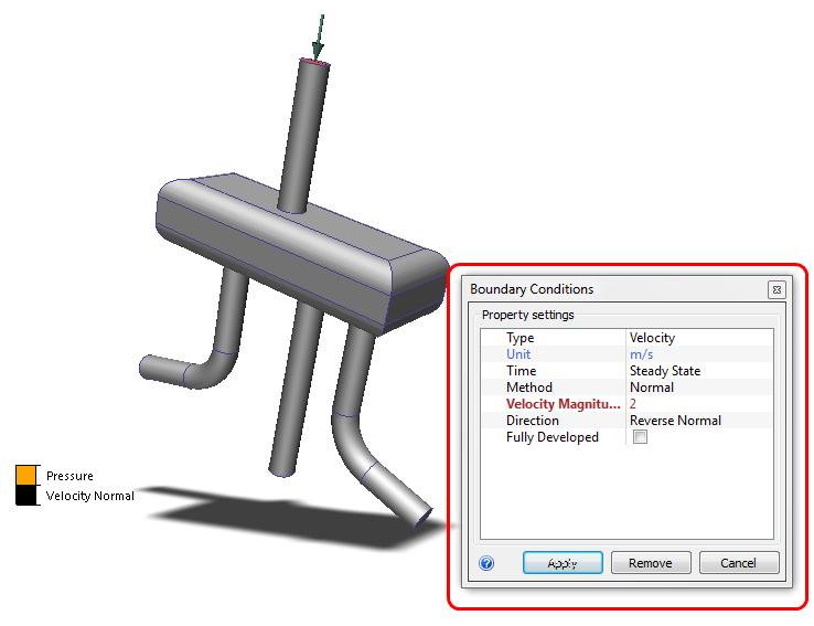
Right click on part (Boundary Conditions task):
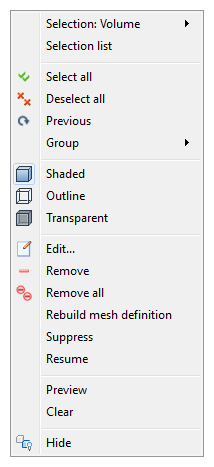
Right click on part (Mesh task):
Results Tasks
On every Results task, use the right-click menus to modify the appearance of the model, part, or results object.
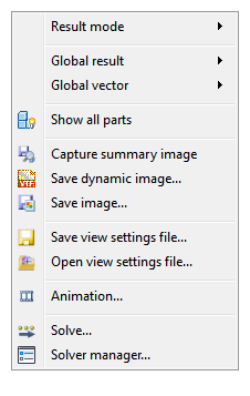
Right click off Model:
Right click on Part:
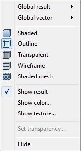
Right click on Plane or Iso Surface (while either Planes or Iso Surfaces task is active):
6. Quick Edit Dialogs
The quick edit dialog is the primary tool for specifying parameters and values for model set up and result extraction. Every task has a unique quick edit dialog that contains fields for task-specific settings. They are an essential workflow element of Autodesk® CFD.
They are several ways to open quick edit dialogs:
- Left click on an entity, and click the Edit icon on the Context Toolbar.
- Right click on an entity, and select Edit....
- In the Design Study bar, right click on a setting or entity, and select Edit....
- In the Design Study bar, double click on a setting or task branch.
- Click Edit on the Ribbon Context panel.
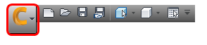
7. Application Menu
Use the Application Menu to manage files, set preferences, and to access recently saved design studies. Click the round icon in the top left corner to open the Application Menu.
Optionally, to learn more about the Application Menu...
8. Quick Access Toolbar
The Quick Access Toolbar is adjacent to the Application Menu (near the top left corner). It is a convenient location for commonly used controls. The default tools in the Quick Access Toolbar are summarized:
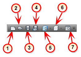
- New: Create a new design study.
- Open: Open a design study or a share file.
- Save: Save all scenarios and designs in the design study.
- Save Share File: Save a reduced-size version of the Design Study file.
- Selection Mode: Specify the type of entity that can be selected. The options are Volume, Surface, or Edge.
- Visual Style: Control the appearance of the model.
- Selection List: Toggle the display of the Selection List.
Optionally, to learn more about the Quick Access Toolbar...
9. Infocenter
Use the Infocenter to log into the Autodesk Network and to access the Subscription Center.
10. Design Study Bar: Manage all aspects of the Design Study with the Design Study bar
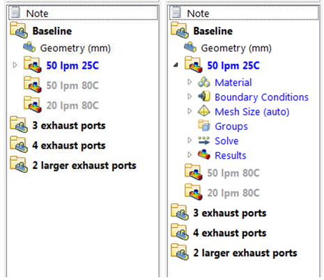
The Design Study Bar is a fully interactive tree-based tool for defining and managing all aspects of the Autodesk® CFD process. The Design Study Bar follows a hierarchical structure that organizes the Autodesk® CFD process into three fundamental levels: Design Study, Design, and Scenario.
Each design study contains at least one design (specific CAD geometry) and each design contains at least one Scenario (collection of materials, boundary conditions, and mesh settings, along with the associated analysis results). Designs are listed in bold black letters and scenarios are shown in bold blue letters. The setup assignments and results are listed in thin blue letters within each scenario. Manage the analyses from this window.
Optionally, click here to learn more about each branch of the Design Study Bar...
11. Decision Center
The Decision Center is a simple yet powerful environment for comparing design alternatives. Use it to identify the design that satisfies your design objectives. The Decision Center is a key part of the results visualization process.
Optionally, click here to learn more about the Decision Center...
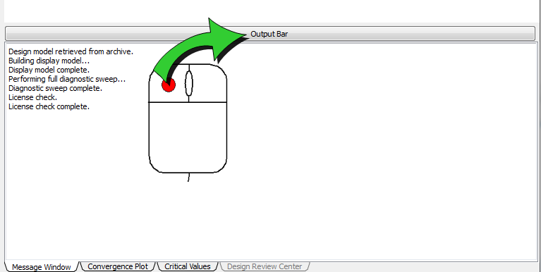
12. Output Bar: View analysis status information and important results data
- Analysis startup and conclusion information is stored in the Message Window tab.
- Monitor analysis progress with the Convergence Plot.
- Compare summary results with the Critical Values tab.
- Compare visual results with the Design Review Center tab.
Collapse the Output Bar as needed:
To expand the Output bar:
13. View Cube
The Autodesk® ViewCube® is a highly interactive, persistent tool for controlling the orientation of your mode. It provides a simple way to select standard (Cartesian-aligned) and isometric views of your model. The ViewCube tool provides visual feedback about the current viewpoint of the model as view changes occur.
You can use the ViewCube to quickly orient in any of 26 pre-set orientations, rotate the model about the Cartesian axes, and reset the model to its default orientation.

By default, the ViewCube appears in one of the corners of the graphics window in an inactive state. When the cursor is positioned over the ViewCube tool, it becomes active.
To orient the model, switch to one of the available preset views, roll the current view, or select the Home view of the model.
You can also customize the appearance and behavior of the ViewCube to your preferences.
14. Selection List
The Selection List displays items that have been selected in the Setup tasks. This is especially helpful for knowing exactly which items are selected.
In the Planes and Iso Surfaces Results tasks, the Selection List displays the list of existing planes or iso surfaces, respectively. In the Wall Calculator, Parts, and Points Results tasks, use the Selection List to interact with the controls of the current task.
To control the display of the Selection List, click the toggle in the Quick Access toolbar:

15. Status Bar: View Results values
- To view numerical results from a model surface, hold Shift + Ctrl, and hover the mouse over the desired location
- To view numerical results on a planar cut surface, hold Shift, and hover the mouse over the results plane.
Values are shown in the Status Bar, located in the lower left corner:

16. Navigation Bar
The navigation toolbar is a collection of several tools for controlling model orientation and the view. It floats over and along one side of the graphics window. To activate a navigation action, click a button on the bar. Some of the buttons have additional tools in a sub-menu. To access these, click the small arrow below the button.
The Basic Workflow
Now that you have toured the entire Autodesk® CFD User Interface, it is a good idea to see how the pieces fit together to form the Autodesk® CFD workflow. In later chapters of this training, we explore in greater detail the tasks referenced below. For now, it is helpful to understand the typical workflow.
Model setup workflow
The Setup tasks all follow a similar workflow. There are several ways to work with the model. You should use the method that is most comfortable.
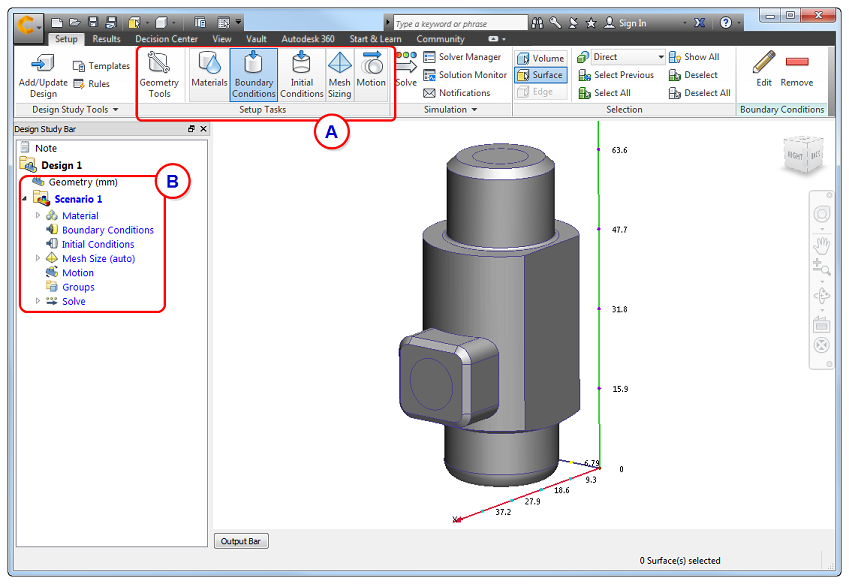
To begin, select the task from either the Setup tab (A) or from the Design Study bar (B):
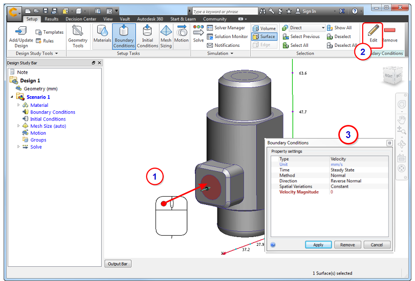
To select and define settings with the Ribbon:
- Left click on the model entity (surface or part).
- Click Edit on the context panel.
- Specify settings in the quick edit dialog.
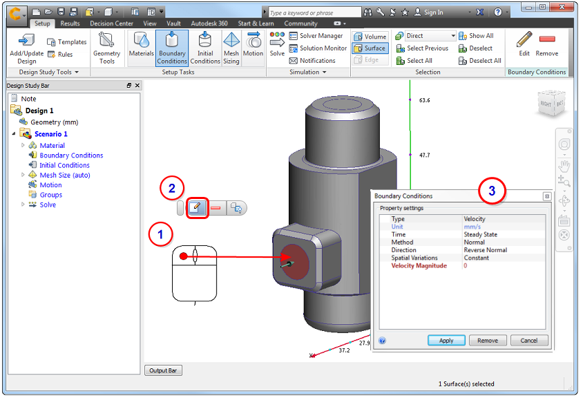
To select and define close to the model:
- Left click on the model entity (surface or part).
- Click the Edit button on the context toolbar.
- Specify settings in the quick edit dialog.
To select and modify from the Design Study bar:
- Right click on the model entity or existing setting in the Design Study bar.
- Click Edit...
- Specify settings in the quick edit dialog.
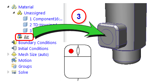
To define and assign:
- Open the quick edit dialog. (Left click and select Edit on the context toolbar.) Alternatively, right click on Material or Boundary Condition in the Design Study bar, and click New material... or New BC..., respectively.
- Specify the settings in the quick edit dialog, and click Apply.
- Drag the unassigned setting from the Design Study bar onto the model entity.