Chapter 5: CAD Connection and Basic Model Interactions
Previous: Chapter 4 | Next: Chapter 6
In this chapter we discuss how Autodesk® CFD manages files and connects with your CAD system. Additionally, we describe the basics of model navigation and entity selection.
What is a Design Study?
Before launching Autodesk® CFD, it is important to understand the concept of a Design Study.
A Design Study is the Autodesk® CFD file structure that groups multiple analyses within a single Autodesk® CFD session. A primary benefit of the Design Study is to facilitate comparison of results. The underlying geometry for analyses in a Design Study can be different, and each unique geometry is called a "Design." Analyses can also have different materials and operating conditions. Each different combination of settings is called a "Scenario." The Design Study hierarchy helps you track and organize these scenarios.
The Design Study is the core of Design Study Automation. It is a hierarchical structure that organizes the Autodesk® CFD process into three fundamental levels:
Design Study
- Every time you use Autodesk® CFD, you are in a Design Study.
- At its simplest, the Design Study contains a single analysis.
- The Design Study is a file system that organizes multiple variables critical to the design process.
- The name of the Design Study only appears on the top bar of the User Interface.
- The Design Study is the framework for the definition and comparison of the multi-level engineering design project.
- Design Studies contain Designs and Scenarios...
Design
- Every unique geometric model is a Design.
- Use Designs to understand the effects of geometry modifications made in the CAD system.
- Create a new design for each geometric variation from your CAD system.
- Each Design can have one or more individual Scenarios that reference it...
Scenario
- A Scenario is an individual analysis within a Design.
- All Scenarios in a design reference the same geometry.
- To understand the effects of different settings (such as boundary conditions or materials), create a new scenario for each different settings case.
Launch from CAD
Autodesk® CFD includes direct launchers for Autodesk® Inventor, Autodesk® SimStudio, Autodesk® Revit, SpaceClaim, Pro/Engineer, UGNX, and Solid Works.
If Autodesk® CFD does not support direct launching from your CAD system, you can often read the file directly into Autodesk® CFD or open the model into Autodesk® SimStudio, and launch into Autodesk® CFD.
To create a new Design Study by launching from CAD
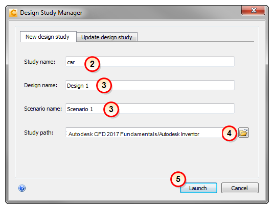
The Design Study Manager is an interactive tool for coordinating your CAD models and Design Studies in real-time.
It is a powerful way to manage Design Studies, Designs, and Scenarios. It allows you to easily update them from your CAD tool without having to exit Autodesk® CFD.
The Design Study Manager opens automatically when you launch Autodesk® CFD from CAD. It is highly versatile, and contains several functions:
- To check for issues in the geometry with the Model Assessment Toolkit, click the command to launch the Active Model Assessment Tool. After completing the assessment, the Design Study Manager opens. To launch directly into the Design Study Manager, click the CFD launch button or menu item.
- Specify a name for the Design Study in the Study name field. The default name is the name of the top level assembly or the part.
- Optionally, change the Design and Scenario names from the defaults.
- The default location of the study is the same path as the CAD model. To change this, click Set path..., and select (or create if necessary) the desired path.
- Click Launch. Autodesk® CFD starts, and the Design Study is created. The first Design and Scenario are listed in the Design Study Bar.
Additionally, use the Design Study Manager for the following:
- Add geometry to a Design Study
- Open an existing design study
- Add a new design to a design study.
We will explore these later in the Fundamentals Training.
Optionally, click here to see an example of creating a new design study...
Optionally, click here to learn more about the Design Study Manager...
Launch from a CAD or Geometry File
You can transfer geometry into Simulation by directly opening a geometry or CAD file. Use this method if the CAD system is not available or if you are using geometry from Vault. This method is often faster than launching from CAD. It is not as well suited for studying geometry variations because settings assigned cannot always be reliable transferred from existing designs to new ones. If you need geometry associativity, it is better to launch from the CAD system.
To create a new design study
- Start Autodesk® CFD either from the Desktop or Start menu.
- Click (Start & Learn > New).
- On the New Design Study dialog, click Browse
- On the Create New Design Study dialog, browse for and select the file, and click Open.
- On the New Design Study dialog, enter a Name for the Design Study.
- Optional: To check for issues in the geometry with the Model Assessment Toolkit, check the Import into Model Diagnostics checkbox.
- Click Create a new design study.
Supported File Types
- Autodesk Inventor (.iam and .ipt)
- Fusion Acis file (.fsat)
- Autodesk (.smb, smt)
- Parasolid (.x_t)
- Acis (.sat) (No higher than version 7.)
- Pro/Engineer assembly and part files (.asm and .prt) (The Granite kernel is used to directly open these files.)
- SolidWorks (.sldasm, .sldprt)
- UGNX (.prt)
- CAD Doctor (.sdy)
- Step (.stp, .step)
- CATIA (.CatPart and .CatProduct)
- IGES (.igs)
- Rhino (.3dm)
- Siemens PLM Files *(.jt)
This performs the same functions as the New icon on Quick Edit toolbar.
Launch from Autodesk® SimStudio
If Autodesk® CFD does not support direct launching from your CAD system or does not read your CAD format directly, you can use Autodesk® SimStudio to prepare the model and to launch into Autodesk® CFD.
- Open the CAD model directly into Autodesk® SimStudio.
- Use the extensive collection of geometry tools to prepare the model for simulation.
- To launch the model, click Autodesk® CFD from the Add-Ins list:

The visible model is launched, and the Design Study Manager opens.
Navigating the Model
Default Mouse Navigation (Rotate/Zoom/Pan)
These are the basic ways to move the model with the mouse.
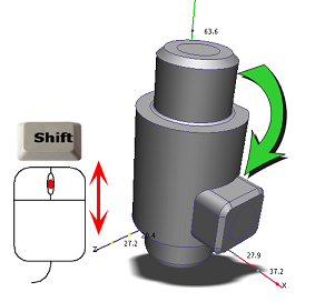
To rotate, press Shift and the middle mouse button, and move the mouse:
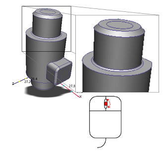
To zoom, roll the mouse scroll wheel:
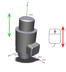
To pan (move), hold the middle mouse button, and move the mouse:
Navigate with the Navigation Tools
You can also move the model with the navigation tools embedded directly within the user interface:
ViewCube:

To rotate the model, position the mouse over the ViewCube and press the left button while you drag the mouse. To change the model orientation, click any face, edge, or corner on the ViewCube.
For more about the ViewCube, click here.
Navigation toolbar:

The navigation toolbar is a collection of orientation tools. It is located on the right side of the graphics window. You can these tools to pan, zoom, and rotate the model.
For more about the Navigation toolbar, click here.
Mouse Navigation Modes:
Autodesk® CFD provides several navigation modes for using the mouse to navigate the model. In addition to the default mode, there are several modes that mimic navigation in the supported CAD tools.
To change the navigation mode, do the following:
- Open the Application menu, and click Options. Click the Navigation tab.
- Select the desired CAD tool from the Navigation Mode menu.
- Restart Autodesk® CFD to activate the change.
Click here for a list of the mouse navigation modes in Autodesk® CFD...
Selecting Objects
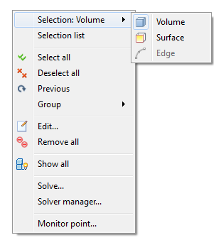
There are several ways to set the selection mode to volume, surface, or edge:
- From the right click menu on the Graphics window:
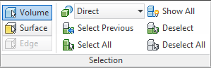
- From the Selection panel
Selection Colors
Specific colors are used to indicate the selection status of entities:
- When the mouse hovers over an entity, it turns green.
- When an entity is selected, it turns red.
- When the mouse hovers over a selected entity, it turns yellow.
When an item is selected, its label appears on the Selection List. To select entities from the Design Study Bar, simply left click on their label in the appropriate branch.
Selection Icons
Use the icons on the Selection panel to select and deselect multiple entities:
![]()


Selection Method
To select multiple entities that are related to another (easily selected) item, select from the Direct menu.
Entities of the selected type highlight as you move the mouse over them. To select all items that are associated with the selection type, click on any highlighted item.
For example, if ten parts are assigned the same material, select Material from this list. As you move your mouse over the model, you will see that all ten parts highlight together because they have the same material. To select all ten, click on one of them.
The selection methods for each selectable entity are:
| Entity | Selection Method |
| Volume | Direct -- Volumes are highlighted and are selected |
| Material -- All volumes that have the same material are highlighted and selected together. | |
| Surface | Direct -- Surfaces are highlighted and are selected |
| Volume -- Volumes are highlighted, and all surfaces touching a picked volume are selected. | |
| Edge | Direct -- Edges are highlighted and are selected |
| Surface -- Surfaces are highlighted, and all edges touching a picked surface are selected. | |
| Volume -- Volumes are highlighted, and all edges touching a picked volume are selected. |
Hiding Objects
Hide an object to gain access to an object behind it.
- To hide an object:
- Left click on it, and click the Hide icon on the context toolbar.
- Right click on it, and select Hide.
- Hold the Ctrl key and middle click on it.
- To show a hidden object:
- Left click off the model, and click the Show all icon on the context toolbar.
- Right click and select Show all.
- Click (Setup tab > Selection panel > Show All).
- Hold the Ctrl key and middle click in the graphics window, off the model.
- To undo and redo hiding and showing objects, hold the Ctrl key and roll the mouse scroll wheel