Exercise 7
Previous: Chapter 14 | Next: Chapter 15
This exercise teaches how to view and measure results on the complete model and on individual parts.
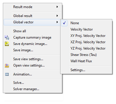
To remove vectors from the display, right click and select Global Vector. Select None from the list.
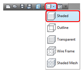
Show velocity distribution on model surfaces by selecting Shaded from the Quick Access toolbar:
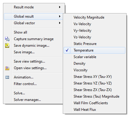
To display the temperature on the model, right click and select Global result. Select Temperature from the list.
To probe for temperature values, hover the mouse over the model. Values are displayed in the Status bar, in the lower left corner.
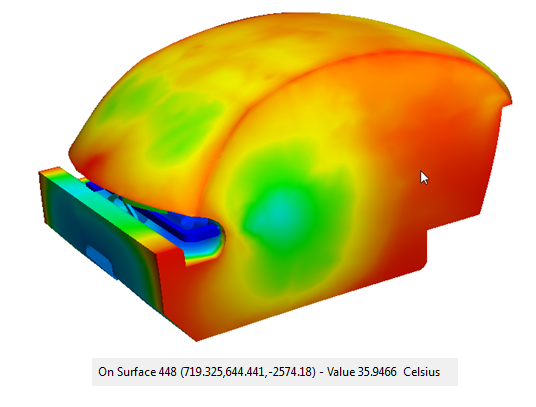 Note: Move the mouse over various surfaces and note the cooler spots near the front registers, on the windshield and rear window. Notice the warmer temperatures near the rear seat and in front of the console.
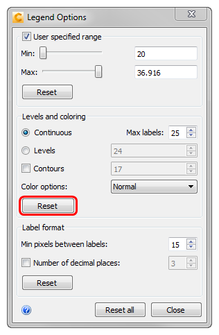
To adjust the minimum and maximum values on the legend, right click on the legend and select Options.
In the Legend Options dialog, enable User specified range. Use the Min and Max sliders to adjust the legend range (to see how this affects the results display). Click Reset when finished.
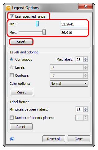
 Note: You can also modify the range by typing values into the fields, and pressing Enter key.Note: To locate a specific temperature range within the model, adjust the legend range.
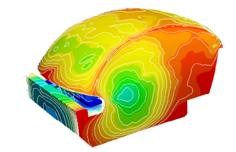
To achieve greater resolution between values, click on Levels or Contours or both. Control the levels and contour values in the adjacent fields. Be sure to click Reset when finished.
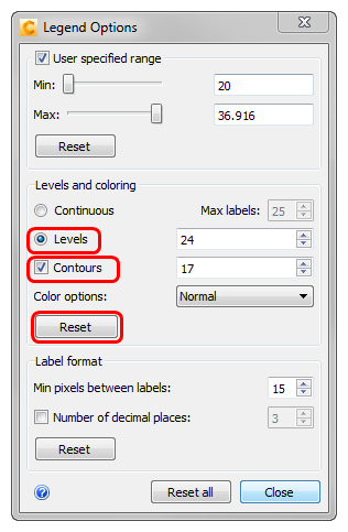
Experiment with modifying the label format and number of decimal places. Click Reset all, and click Close to exit the Legend dialog.
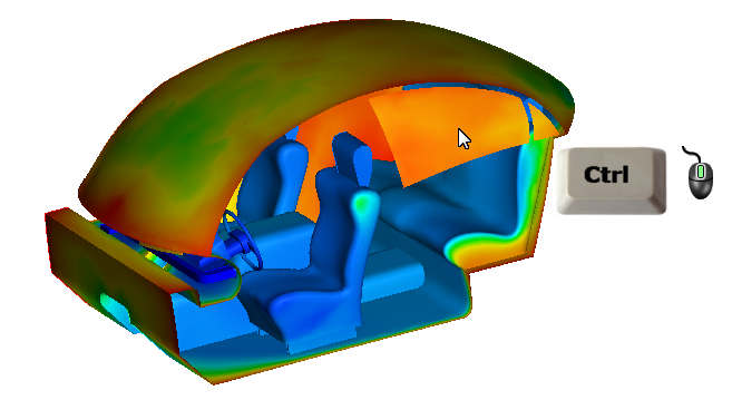
To view the results inside the cabin, begin by clicking View (tab) > Appearance (panel) > Surface Blanking.
Note: This toggles between hiding surface and hiding volumes when viewing results.To reveal the cabin interior, hide the side surfaces. (Hold the Ctrl key and click the middle mouse button on the desired surfaces.)
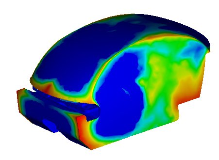
Right click on the legend and choose Options. From the Color options menu, select Thermal 2.
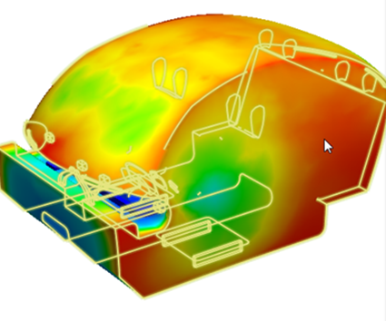
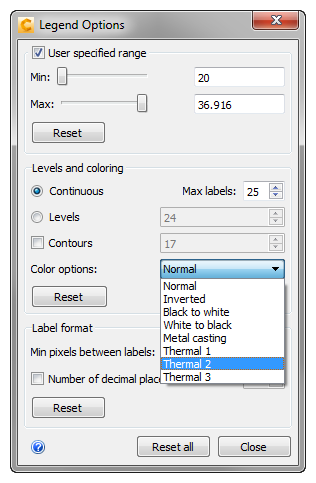 Note: Thermal 2 emulates a thermal camera, which is a very useful way to present the temperature distribution throughout the cabin:
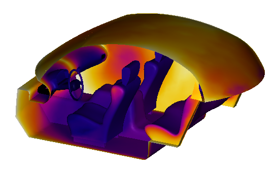
To reset the view, click Reset, and close the dialog. Right click off the model, and click Show All.
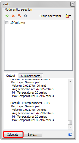
Click Parts on the Results tab.
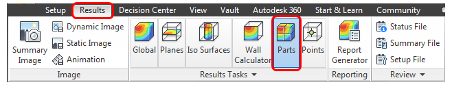
To compute the temperature of the air, select the cabin air volume. Click Calculate in the Parts selection window, scroll down to the last iteration, and note the average, maximum, and minimum temperatures: