Exercise 4
Previous: Chapter 10 | Next: Chapter 11
This exercise teaches how to automatically assign the mesh, preview it, and customize the mesh distribution for your particular design study.
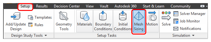
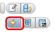
Click Mesh Sizing on the Setup tab:
Right click off the model, and click Show All. Rotate the model to see all of the car.
Note: Because we are only studying the air in the cabin, we can suppress all other parts from the model. We begin by suppressing all parts, then resume the air in the cabin for meshing:Right click off the model, and click Select All.
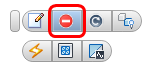
Left click off the model, and click the Suppress icon on the context toolbar.
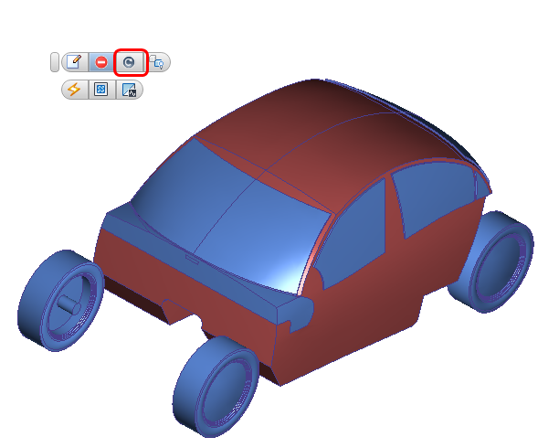
 Note: Suppressed parts are colored blue.
Hide the car body. Select the cabin air volume and click Resume from the context toolbar.
 Note: Resumed parts are colored gray again.
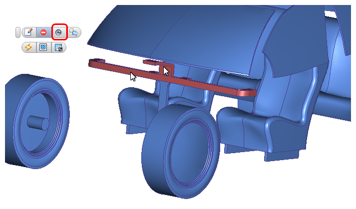
Hide the cabin air volume and the console to reveal the ductwork air parts. Select the upper air part and the duct flow region and choose the Resume icon from the context toolbar.
Left click off the model, and click the Autosize icon from the context toolbar.
 Note: Cyan dots that indicate the locations of the mesh nodes are drawn on the edges of the three air volumes to be meshed. Dots that appear on suppressed parts are on edges that are shared with the cabin air volume.
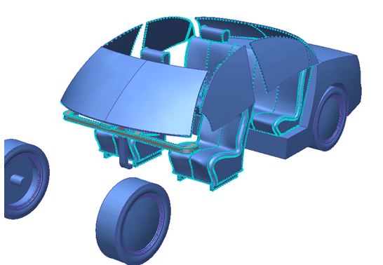
To determine if the mesh needs to be modified, check the Approximate Element Count. Right click off the model, and click Edit... Note the element count.
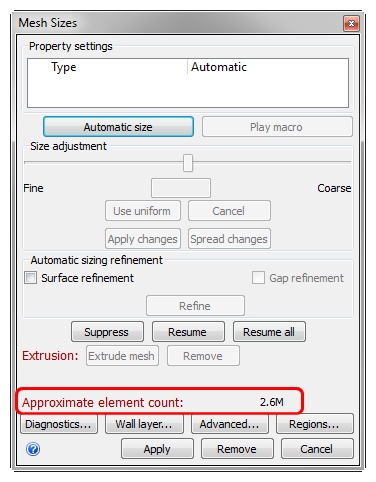 Note: The number you see may be slightly different, depending on slight variations in the model due to the originating CAD system.Note: Recall that approximately 2 GB of RAM are required for every million elements.
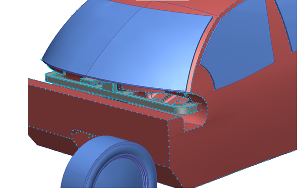
Observe the mesh distribution in the model. Notice that the mesh is too coarse in the duct and too fine on the seats.
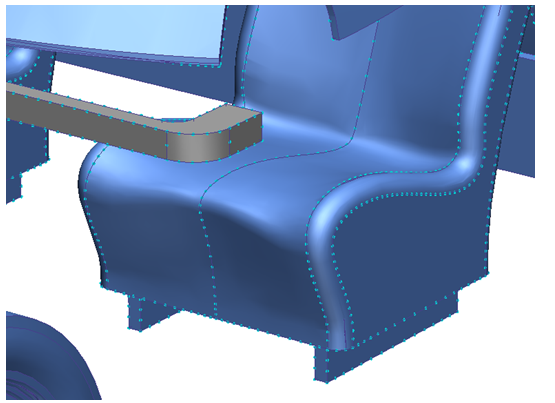 Note: The mesh preview shows one node across the thickness of the duct. Better results are achieved with 3 to 4 nodes across important passages so we will refine the mesh here. By contrast, the seats contain a finer mesh distribution. Because the mesh distribution on the interior surfaces do not heavily influence the mesh in the flow regions, coarsening the mesh here will reduce analysis resources and time.
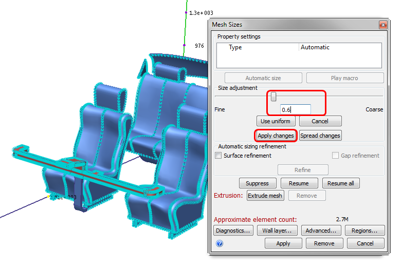
Select the two volumes of air in the ducts. In the Mesh Sizes dialog, drag the Size adjustment slider to approximately 0.6. Click Apply changes.
Show the cabin air part:
Press Ctrl and roll the mouse wheel away from you until the cabin air appears
Or
Right click and select Show All. Right click on the car body and hide it
Select the cabin air part. In the Mesh Sizes dialog, drag the Size adjustment slider to approximately 2 (or type 2 in the field and press the Enter key). Click Apply changes.
To see the new approximate element count, click Spread Changes in the Mesh Sizes dialog. Note the reduction from the original estimate.
Note: Spread Changes recalculates the mesh distribution based on changes made to individual parts, surfaces, and edges. To see the new mesh distribution and the approximate element count, click Spread Changes. Note, however that Spread Changes is automatically applied when the mesh is generated.Note: When considering how fine to make your mesh, remember that it is usually easier to start with a coarse mesh and then refine it. This is typically the most economical use of your time and resources.To generate the mesh, right click on the Mesh Size branch in the Design Study Bar and choose Generate mesh. Click Yes in the confirmation dialog.
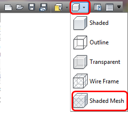
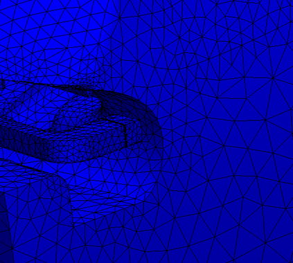
Note: The mesh for this model takes approximately 3 minutes to generate and load results into the Autodesk® CFD interface. Your time may vary slightly.Note: When the mesh is complete, the model color will change to blue, and the last line of the Message Window will be “Analysis completed successfully.”To view the mesh , click Shaded mesh from the Quick Access toolbar:
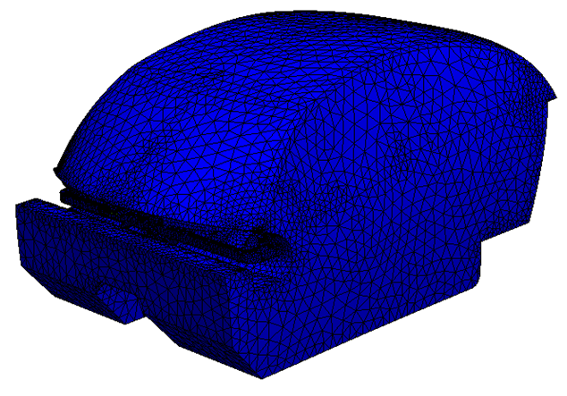
 Note: Note that the suppressed parts are not meshed. Only the three air volumes are meshed. Also notice that the air volumes in the ducts are finer than elsewhere in the model.
Scroll up in the Output Bar to note the final Element Count.
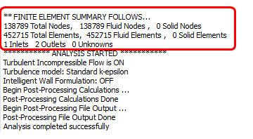 Note: The number you see may be slightly different, depending on slight variations in the model due to the originating CAD system.