Chapter 4: CAD Modeling
Previous: Chapter 3 | Next: Chapter 5
What should the CAD model look like?
An effective simulation starts with good CAD techniques both in terms of model integrity and proper creation of the flow region. The first step is to design your CAD model for the flow analysis. This means modeling the flow geometry and optimizing the model for simulation.
Optimizing the Model for Simulation
The Problem:
- Production-level geometry can contain gaps, interferences, fasteners, and very small features.
- These features are often necessary for manufacturing, but can add unnecessary complexity for simulation.
The Solution:
- To save time and computer resources, eliminate these features if they are too small to affect the results of the simulation.
- For large assemblies, consider analyzing only critical portions of the design. This can accelerate the analysis process.
- In some cases, it is faster to create a new, simpler version of your design to focus on the key areas of study.
Steps you should always take to prepare the geometry:
- Eliminate gaps that prevent void filling. These include clearances between parts, sheet metal reliefs, and fastener holes.
- Eliminate fasteners that do not impact flow or heat transfer.
- Reduce very large assemblies to include only vital components.
- Eliminate interferences. Examples include press-fits and improper mates.
Steps to help reduce the analysis time:
- Eliminate very small features that do not affect the analysis results. These include:
- Small fillets
- Chamfers
- Very small parts
- Fill small gaps in the flow region that are not important.
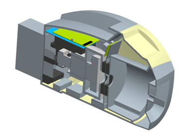
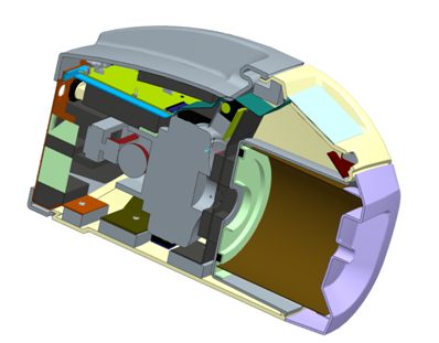
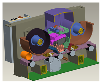
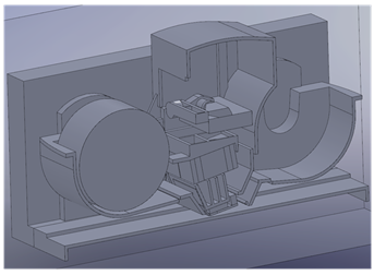
Example features that can be removed and do not affect the Simulation
Very small features as well as interferences, gaps, and fasteners can generally be removed from the model unless they significantly affect the flow or thermal behavior within the device. Here are three examples of geometry created for production and the corresponding simplifications that are suitable for the CFD simulation:
Production | Simulation |
 |  |
|
|  |
|
|
|
Tools for assessing the Model
Because many geometric issues are very small, they can be difficult to locate, especially within a complex model. The Model Assessment Toolkit interrogates the geometry to identify a series of known geometric issues that frequently occur in CAD models.
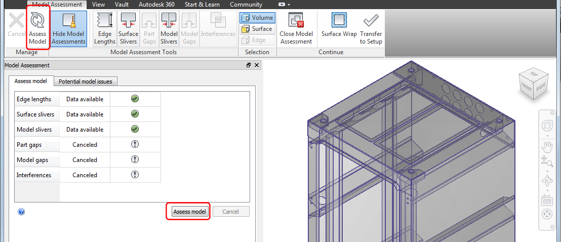
For each part, the Toolkit looks for these issues:
- Small edge lengths
- Surface slivers
- Part gaps
For each assembly, the Model Assessment Toolkit looks for these issues:
- Model slivers
- Model gaps
- Interferences
The Toolkit identifies issues, but does not provide tools for fixing them. It's usually best to resolve issues in the CAD system or in Autodesk® Sim Studio. In some cases, issues are not important and can simply be ignored. In other cases, they should be addressed to reduce the chances of meshing errors and potentially much longer simulation times. It often required engineering judgement to determine what should be fixed.
You can start the Model Assessment Tool when launching from a CAD system by selecting the Active Model Assessment Tool option in the Autodesk CFD launch commands. When opening a geometry file, check the box called Import into Model Diagnostics on the New Design Study dialog.
To learn more about the Model Assessment Toolkit, click here.
Modeling the Flow Geometry
For Autodesk® CFD to study the flow in a design, there must be a model of the flow region. Most CAD models do not include this by default, but there are three different ways that this model of the flow region can be created. Knowing which one best suits your analysis will influence how you prepare your CAD model:
Generate the Flow Model in your CAD system
In your CAD system, you may choose to create a part or parts that represent the flow region.
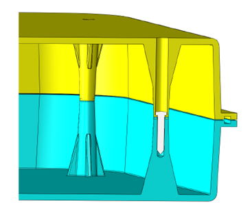
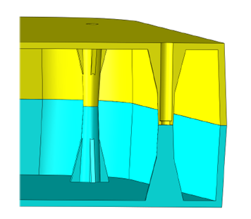
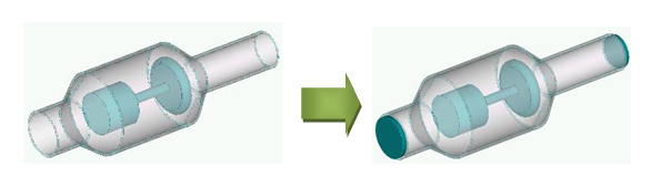
For internal flows such as pipes, valves, and electronic enclosures, this often means creating a volume for the flow:
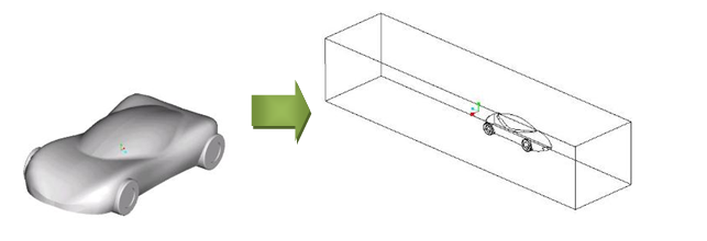
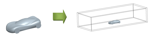
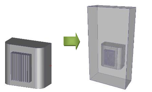
For external flows such as over a vehicle or around an exposed module, this usually means creating a box that encompasses the entire model:
Advantages:
- The flow geometry is part of the CAD model.
- You control the size and position of the flow volumes.
Disadvantages:
- The flow geometry inside a complex model can be difficult to create.
- Need to eliminate any interferences between the flow volume and the other parts.
Ensure the void is airtight, and Autodesk® CFD creates the flow part
Autodesk® CFD automatically creates parts to fill any void space in a model. These are included only in the design study, not in the CAD model.
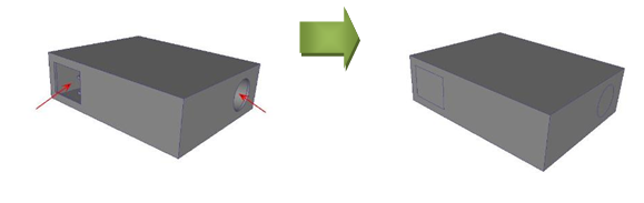
For internal flows such as pipes, valves, and electronic enclosures, create "caps" to cover the openings. They ensure the void is "air tight" so Autodesk® CFD can create the flow volume.
For external flows such as over a vehicle or around an exposed module, enclose the model with a box. This causes Autodesk® CFD to create a flow volume between the box and the model.
Advantages:
- This method is generally simple to perform.
- The exact shape of the flow geometry is captured and interferences are not an issue.
- Cap volumes created in CAD are used as part of the flow region. You can vary the thickness of the caps to control the location of your boundary conditions. Create thicker caps to move the boundary condition further upstream from the object; use thinner caps to move the boundary condition closer.
Disadvantages:
- Caps are additional parts in your CAD model, and must be saved with the other CAD model files.
- For external flows, you can include the box as part of the flow or exclude it by suppressing it. If you suppress it, be sure to apply boundary conditions correctly to the generated flow region.
- Some larger assemblies may have gaps that are difficult to detect and which may prevent correct creation of the fluid volume.
Use the Geometry tools in Autodesk® CFD to Generate the Flow Model
You can add the flow volume directly to the simulation model.
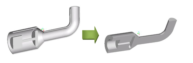
For internal flows such as pipes, valves, and electronic enclosures, use Void Fill to build surfaces that close planar openings. After all openings are closed, and the space is "airtight," create the internal volume that fills the void.
For external flows such as flow over a vehicle or around an exposed module, use External Volume Creation to create a flow region around your model.
Advantages:
- Autodesk® CFD does the difficult work for you.
- Exact shape of the flow geometry is captured and there are no interferences between the device and the region.
- There are no additional parts needed in your CAD model.
Disadvantages:
- Surface caps in Void Fill operation can only be planar.
- Caps also become part of the fluid volume, so boundary conditions are applied directly to the flow region. This may be too close to the flow region for some analyses.
- External Volumes cannot be precisely sized and located relative to the model. This is suitable for some analyses, but not all.
Optionally, click here to learn more about Geometry Tools...
Use Surface Wrap to Create the External Volume
An additional technique for creating an external volume is to use a "Surface Wrap." It works by creating a volume that surrounds the external surfaces of the model. The individual parts of the model are effectively merged together, so this technique is most applicable for external flow simulations in which the internal parts do not participate in the simulation.
To activate Surface Wrapping, start Autodesk CFD, and click New. Browse for a CAD or geometry file, and select the option to Surface Wrap. This opens the Surface Wrap environment in CFD. You can define the size of the surrounding volume, finalize the volume, and proceed to the setup environment. The simulation model behaves as an assembly with the wrapped solid parts wrapped together into a single part inside of the newly created surrounding flow volume.
Click to learn more about Surface Wrapping...