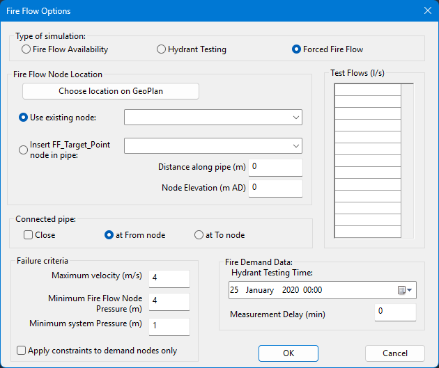
This dialog view lets you set up a forced fire flow simulation to test a selection of flows at a single fire flow target point. Each flow is tested in turn against a number of test parameters. A
Forced Fire Flow report is produced that includes details of pressures at the target point for each test flow.
The fire flow target point may be either an existing network node, or a location along an existing network pipe. For each test flow, a demand equal to the test flow will be applied at the target point location. (In the case of the fire flow target point being along a pipe, demand will be applied at a temporary node inserted into the pipe. The location of the temporary node will be displayed in the GeoPlan window of the Forced Fire Flow results.)
The forced fire flow simulation is performed as a series of snapshot simulations.
This dialog view is opened by selecting
Forced Fire Flow on the Fire Flow Options dialog.
| Item
|
Description
|
|---|
|
Fire Flow Node Location
|
|
Choose location on GeoPlan button
|
Selects a target point location on a GeoPlan of the network selected in the
Schedule Hydraulic Run view.
A GeoPlan window of the network will be opened if it is not already open.
The mouse pointer will change to the hydrant pointer  .
You can now click a node or pipe in the network. The fire flow node location options (below) will automatically be set according to the location selected.
|
|
Use existing node
|
Select this option to use an existing network node as the fire flow target point.
|
|
Insert FF_Target_Point node in pipe
|
Select this option to insert a temporary node to be used as the fire flow target point into an existing network link.
|
|
Distance along pipe
|
Distance along pipe selected in the
Insert FF_Target_Point node in pipe dropdown from the pipe's
To Node.
Defines the location at which the temporary fire flow target point will be inserted.
|
|
Node Elevation
|
Elevation of target point node when inserting a node in a pipe.
Node elevation will be set automatically to the weighted average of the elevations of the nodes at the pipe to be split.
Alternatively, if the elevation of the target point node is known, the default value may be overwritten.
|
|
|
Connected pipe
|
Option to close the pipe on either the From or To side of the fire flow target point.
Note: This option can be applied only if the target node has only two attached pipes that have a consistent direction.
|
Close
|
If checked, enables the close options.
|
|
at To node
|
Closes the pipe that has the fire flow target point as its
From Node ID.
|
|
at From node
|
Closes the pipe that has the fire flow target point as its
To Node ID.
|
|
|
Test Flows (grid)
|
You can enter up to twenty flows in the grid. Each flow will be tested in turn at the fire flow node location.
|
|
Failure criteria
|
Each flow in the Test Flows grid will be tested against the failure criteria.
|
Maximum velocity
|
Maximum allowable velocity in the network.
|
|
Minimum Fire Flow Node Pressure
|
Minimum allowable pressure at the fire flow target point.
|
|
Minimum system Pressure
|
Minimum allowable pressure in the network.
|
|
Apply constraints to demand nodes only
|
If checked, enforces
Maximum velocity and
Minimum system Pressure failure criteria at nodes with assigned demand only.
If this box is unchecked, all basic nodes will be tested against failure criteria. Reservoir, well and fixed head nodes will be excluded from the check.
|
|
|
Fire Demand Data
|
|
Hydrant Testing Time
|
Defines the point at which the hydrant test begins during the simulation period. This must be between simulation start and end time.
|
|
Measurement Delay
|
You can use this to set a delay between the start of the forced fire flow test and the point from which results will be calculated i.e. the point when measurement of the forced fire flow test's effects on the network occurs/begins.
This is useful for fire flow tests on nodes that are downstream of control objects which use control types that react to changes in conditions on the following simulation timestep, namely
PRVs and objects controlled via
UPC. In this situation, it is recommended to
set Measurement Delay at 1 min so that the network can properly react to the increased flows from the fire flow test, whilst having minimal impact on the overall network mass balance.
This can also be used when understanding the impact of an extended (more than a single timestep) fire flow event on the network is required, as the network simulates the outflow from the fire flow test over the entire delay period. For example, a network that feeds an area undergoing a fire flow event via a small reservoir/tank may have that storage depleted within a short time window, resulting in the minimum flow and/or residual pressure requirements not being met after that point; setting a measurement delay covering the required/average fire flow event period enables this to be tested.
|
|