The Geometry Cleanup Settings dialog box controls how geometry errors are scanned and fixed in a drawing. You can choose error types, set tolerances, and import or export a settings file for future use. Settings are stored in the user profile and persist across drawings for the same account.
Display the Geometry Cleanup Settings dialog box
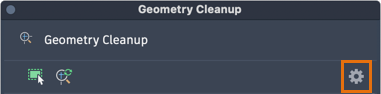
- From the Geometry Cleanup palette, click the Settings icon.
Specify error types and tolerances for Geometry Cleanup
- Display the Geometry Cleanup Settings dialog box.
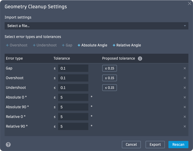
- In the Geometry Cleanup Settings dialog box, add or remove the error types for which you want to check by doing the following:
- Add or remove an error type: Click the '+' next to the error type to add it.
- Remove an error type: Click the 'X' at the end of the row to remove it.
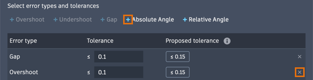 Note: Overshoot, Undershoot, and Gap errors can be toggled on or off. Absolute Angle and Relative Angle errors can be added with custom angle values from 0° approaching 180°. There is no limit to how many Absolute Angle and Relative Angle errors can be added, but duplicate values will not be processed.Tip: Removing unnecessary error types can speed up the scanning time for selected geometry.
 - Set the tolerances, or thresholds for error identification, for each error type. Errors within the tolerance from their perceived "correct" location will be identified as errors; errors exceeding the tolerance will be treated as intentional. There are two options:
- Accept proposed tolerance (recommended): In the Proposed tolerance column, click the suggested value to set the tolerance based on the drawing's geometry. Proposed tolerances are calculated from the average length of lines and polyline segments in the drawing.
- Edit tolerance: Under the Tolerance column, enter a numeric value for the error type. This value must be greater than 0.000100 and up to 6 decimal places. Length-based tolerances are unitless and angle-based tolerances use degrees. Any tolerance value smaller than 0.000100 will be autoconverted to 0.000100.
- Click Scan.
Import a .gcs settings file
- Display the Geometry Cleanup Settings dialog box.
- Under Import settings, click Browse a file.
- In the Load Settings dialog box, browse to a .gcs file and select it.
The imported settings from the .gcs file are shown in the Settings dialog box.
Note: The original default settings can be restored by deleting the
default.gcs file located in the
%LOCALAPPDATA%\Autodesk\GeometryCleanup folder.
Export a .gcs settings file
- Display the Geometry Cleanup Settings dialog box.
- Click Export.
- Choose a location and file name to save the .gcs settings file.
Scan or rescan for errors
- Click Scan or Rescan to start scanning geometry with the current settings.
The settings dialog box closes, and scanning begins on the selected error types and tolerances.