|
From version 2027.2 onwards, Subgrid Sampling is no longer a Tech Preview. Users of earlier versions of InfoWorks ICM will continue to use the Tech Preview version, which supports a limited set of modelling capabilities, network objects and mesh functionality. |
Subgrid Sampling time step method
The time step calculation method for subgrid 2D elements is based on a Courant Friedrichs Lewy condition. A wave speed and characteristic distance is calculated for each 2D element (see Equation 4 in Basic 2D Hydraulic Theory), which are used to estimate the time step at the 2D element. The 2D time step for a 2D zone is calculated as the smallest of the time steps for its 2D elements.
A method for the time step calculation is essential to ensure the numerical stability of the 2D engine and is specified in the simulation parameters. There are several options for estimating the time step at subgrid 2D elements, which are listed below in descending order from more aggressive to less aggressive time step calculation methods. Face depth is the default option as it ensure stability in any flow conditions by restricting the interaction between waves in a 2D element. The other methods may produce performance gains at the cost of numerical stability and volume balance errors. If you select a different option for the Time step method, it is essential to ensure the model is stable by checking the volume balance report in the log file for the relevant simulations.
- Original
Flow celerity is based on the average depth across the whole subgrid 2D element.
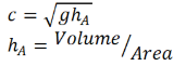
- Average depth
Flow celerity is based on averaged depth on the wetted part of the subgrid 2D element.
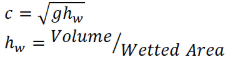
- Max depth
Flow celerity is based on the maximum depth on the subgrid 2D element, which is the maximum depth across the entries in the volume level table for a specific level.

- Max depth and wetted area
Flow celerity is calculated as in Max depth, but the characteristic mesh element length is estimated as the square root of the wetted area.
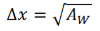
- Face depth limited
Flow celerity estimation is based on the maximum depth across the faces of the subgrid 2D element.

The characteristic mesh element length is estimated as the maximum between:
- The square root of the characteristic area, with the characteristic area being estimated as the max between the wetted area in the element Aw, and the minimum spilling area As, which is the wetted area where the first spillage towards a neighbour 2D element occurs.
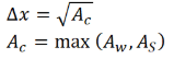
- 2* characteristic area / characteristic perimeter, where the characteristic perimeter is the maximum between the wetted perimeter (Pw) and the minimum spilling perimeter (Ps), which is the wetted perimeter where the first spillage towards a neighbour 2D element occurs.
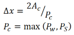
- The square root of the characteristic area, with the characteristic area being estimated as the max between the wetted area in the element Aw, and the minimum spilling area As, which is the wetted area where the first spillage towards a neighbour 2D element occurs.
- Face depth (default)
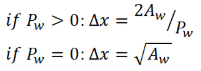
Flow celerity estimation is based on the maximum depth across the faces of the subgrid 2D element.
The characteristic mesh element length is estimated as 2*wetted area (Aw) divided by wetted perimeter (Pw) if the wetted perimeter is > 0. Otherwise it is the square root of the wetted area.
Depth tolerances
The volume/level tables, which determine storage in a subgrid 2D element, can be simplified using a modified Ramer-Douglas-Peucker algorithm to ensure that depth estimation errors are within set tolerances.
The allowed depth estimation error for a given depth is set by the percentage depth tolerance, and depth estimation error can also be limited between a minimum and maximum depth tolerance.
If an unsimplified volume/level table retrieves a 1m depth for a specified volume, and the percentage depth tolerance is set to 5%, the depth estimation error in the simplified table is set to 5cm. Therefore the simplified volume/level table is forced to retrieve a depth value between 0.95 and 1.05m. Additionally, if the minimum depth tolerance is set to 1cm and the maximum is 2cm, the range of valid depth estimations from the simplified volume/level table will be further restricted to the range 0.98 and 1.02m.
As volume/level table simplification has minimal impact on engine performance no tolerances are set by default. However, using simplified tables will reduce the memory footprint and may allow meshes, with more triangles, to be simulated in models containing Subgrid Sampling 2D zones. This can be beneficial particularly in the case of simulations running on a GPU card, where the memory size of the model is mapped directly onto the memory of the GPU card. Volume/level table simplification is performed if any of the following depth tolerance properties are specified in the simulation parameters:
- Min depth tolerance (de_min)
Minimum allowed depth difference between original and simplified volume/level table. This values overrides the value specified by the percentage depth tolerance.
- Max depth tolerance (de_max)
Maximum allowed depth difference between original and simplified volume/level table. This values overrides the value specified by the percentage depth tolerance.
- Percentage depth tolerance (PDT)
Depth percentage error allowed when simplifying volume/level tables.
For instance, if the original table retrieved a 1m level for a given volume, and the percentage depth tolerance is set to 1%, the maximum allowed difference in the level estimation between the original and simplified volume/level tables will be +/- 1cm.
The allowed depth estimation error for a volume/level table entry is:

where d represents the depth from the unsimplified volume/level table