To Create Slots
Quickly place slots using presets, or specify the slot dimensions, insertion point, termination, and other options using the property panel.
What's New: 2027
Steps to create slots
Click 3D Model tab
 Modify panel Slot
  .
.Optional: - Check the panel menu
 to see if the options that you want are active.
Optional: Specify a preset If there are no presets or the preferred one doesn't exist, continue the process specifying the needed slot parameters.
Note: When finished specifying the parameters and click OK, a preset named Last Used is created automatically. You can continue to use the preset or save it to a specified name. Parameter tolerance values are saved in the preset.Input Geometry group
No unconsumed sketch
An unconsumed sketch is not required. Select a face or sketch point (end or mid). The selection establishes the sketch plane, creates a sketch, places a center point at the location clicked, and previews a slot.
Existing unconsumed sketch
If a single unconsumed sketch is present, any center points in the sketch are preselected and a slot feature previews at each center point. Use Ctrl+click to deselect any center point. Where multiple unconsumed sketches exist, you must select which sketch you want to use for the slot feature.
Workplane
Clicking a workplane creates a sketch on the plane, places a slot center, and previews the slot feature. You reposition the feature using the manipulators or dimension relative to linear edges.
To limit the selection to existing points, turn OFF the Allow Center Point Creation option.
Note: The last used state for the option is remembered. ON (default), you can add center points randomly on a part face.
 OFF, you can only select sketch center points or sketch points in an existing sketch.
Positions
Tip: If your design workflow uses one sketch with many slot centers for slots of various sizes, you can quickly deselect all selected slot centers using the Clear Selections button at the end of the Positions list.
Specify the slot position on a face or workplane by clicking anywhere on a planar face or workplane. The slot center is placed where you click.
Drag an unconstrained slot center to reposition it or explicitly position the slot with reference to model edges:
Click a reference edge and enter a distance. Repeat with another edge.
Note: To leverage existing sketch dimensions, when editing a dimension, click the dimension you want to use.To use a dimension from another feature, click the arrow at the right end of the dimension field and choose Select Feature Dimension. Select the feature having the dimension you want to use and then the dimension.
To create concentrically positioned slots, while placing a slot, click the curved edge or face the slot is to be concentric with.
When placing a slot on a workplane, slot depth is measured from the workplane.
To remove a slot center from the selection and retain it in the sketch, use Ctrl + click and select the slot center.
To remove the slot and slot center, select and delete the slot center point.
To clear the selection, use the Clear Selections button.
Solid
Displays when there are two or more solid bodies in the part file, click the Solids selector and select one or more participating solid bodies.
Direction
Specify slot orientation choosing from
 Horizontal (default),
  Vertical, or
  Custom. Click the selector or the Custom icon and then, click an edge or face to orient the slot.
- Edge, the long axis of the slot aligns with the selected edge.
- Face, the long axis of the slot is perpendicular to the selected face.
Rotation
Enter an angle in the value field to orient the slot relative to the Direction. Click Flip direction
 to reverse the angle.
Type.
Provides additional slot parameters. Choose from filleted or square corners. With filleted there are additional seat options for None, Counterbore, Spotface, or Countersink.
Fillets specifies whether the slot is created with or without rounded ends.
 (Fillets) Slot ends are rounded using a radius equal to one-half the width of the slot.
 (Sharp Corners) Slot end faces are perpendicular to the slot sides. The corners do not have fillets.
Hole specifies the purpose for the hole. Choose from
 (Simple Hole) Slot is defined with parameters in Behavior group.
 (Clearance Hole) Slot width is defined by specifying a fastener size.
Specify the fastener by selecting values in the following dropdown lists:
Standard specifies the fastener standard. Select from a list.
Fastener Type specifies the fastener type. Select from a list.
Size, selects the fastener size from a list.
Fit, specifies the clearance slot fit (Normal, Close, or Loose) relative to the selected fastener.
Note: Fastener information can be included in slot notes in drawings.To manage clearance data see Clearance data section in To Work with Thread Data Spreadsheet
Seat specifies whether the hole will be plain or have a specific mating feature, usually related to fastening components. The choices are:
 None is used to define a simple slot.
 Counterbore slots have a specified diameter, counterbore diameter, and counterbore depth.
 Spotface slots have a specified diameter, spotface diameter, and spotface depth. Measurement of the slot depth starts from the bottom of the spotface.
 Countersink slots have a specified slot diameter, countersink diameter, countersink depth, and countersink angle.
Behavior
Center Marks specifies the annotation style for the slot feature. Choose from...
 No Mark
 Length Mark, a center line along the long axis of a slot.
 Center Mark, placed at the center of the slot feature.
 Arc Centers Mark, placed at the centers of the slot end arcs. Available only for filleted slots.
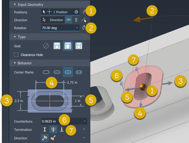
Slot Parameters
An image displays based on the Center Marks selection. The related value fields display below the image. Specify the values as needed or use the manipulators to define the feature. The feature previews in the canvas.
- Common parameters, Slot Width and Depth, are used for all slots.
- Counterbore Width and Depth, used for counterbore and spotface slots.
- Countersink Angle, countersink slots only.
The following example identifies the Spotface slot parameters with corresponding manipulators.
Termination
 Distance defines the termination method for the hole. Uses a positive value for the slot depth. Measures depth as perpendicular from the planar face or workplane.
 Through All extends a slot through all faces.
 To terminates a slot at the specified planar face. Select the surface on which to end the slot termination.
- Click the To Surface selector, select the face on which to terminate the slot.

- If the slot doesn't intersect the termination face,
 Extend To is automatically turned on. If needed, select it turn it off.
Depth displays if Termination is set as Distance. Specify the slot depth.
To Surface displays if Termination is set as To. Select a termination face.
Direction displays when using Distance and Through All termination options.
 Default specifies the slot direction as going into the selected face.
 Flipped reverses the slot direction.
End Mill Specifies the slot bottom face treatment for blind slots. Choose from
 Flat or
  Angle (default is 31 degrees).Note: When creating blind slot features, specify the End Mill type to define how the slot bottom will be machined. Choose 'Flat' for slots with flat bottoms created using flat end mills, or select 'Angle' for slots requiring angled bottoms. When using the Angle option, set the Point angle (default 90°) to match your end mill's tip geometry for accurate slot depth calculations."
Advanced Properties are additional options:
iMate: Select to place an iMate automatically on the slot being created. To learn more about iMates see iMate Fundamentals.
Extend Start: Select to extend the start face of a slot to the first place where there is no intersection with the target body. Extend Start removes a fragment resulting from the creation of the slot. If the result is not desired, deselect Extend Start to remove the result.
Note: For multi-body parts, Extend Start does not extend into a secondary body. An exception to this behavior occurs when the secondary body intersects with the slot body volume being removed. The intersection area is removed.
Click OK, or to continue using the slot command click Apply and Create new
 . You can use Ctrl+Enter instead of clicking OK.
Using the Breadcrumb method to add a slot
- Click the Sketch breadcrumb text to edit the sketch. You are placed in the Sketch environment with the slot previewing in wireframe.
- Add a slot center
- Click the Slot feature breadcrumb text and the slot is added.
Value fields display in the property panel and the in-canvas Edit control. Either can be used to specify the dimension value or the equation to use for the value. You can also edit the parameters in the canvas or graphics area.
Value fields have a flyout menu for recently used values and other tools to specify input. The choices include:
- Measure - activates the Measure command and uses the measured value as input to the field.
- Select Feature Dimension - click the feature that has the dimension you want to use, then select the dimension you want to use. The selected dimension parameter is assigned to the value field.
- Tolerance... - displays the feature Tolerance dialog for your use.
Editing slot Features
In the model browser, edit a slot feature by doing one of the following:
- Double-click the feature node.
- Right-click the feature node and select Edit Feature.
- Set the Select Priority to Select Features and double-click a slot feature.
The property panel displays and you can modify the feature parameters.
Delete slot Features
When you delete a slot feature you can also delete the underlying sketch containing reference dimensions and projected geometry.
To delete a slot feature do one of the following:
- In the model browser, right-click the feature node and select Delete.
- Set Selection Priority to Feature Priority and select the slot feature. If desired, continue to make selections in the Delete Features dialog and click OK.
Edit Feature and Sketch Names Using the Breadcrumb
When creating or editing a slot feature:
- Click the breadcrumb text you want to edit to activate the text.
- Click the text again to enter Edit mode.
- Modify the text.
- Press Enter to commit the change.
You can convert hole features to slot features using the Convert to Slot command on the hole feature right-click menu. The hole is converted to a slot and the property panel displays so you can modify the slot parameters as needed. See To Create Holes.