Energy settings control how the energy model is created from the architectural model.
To open the Energy Settings dialog, click Analyze tab Energy Optimization panel
 (Energy Settings).
Mode
Revit offers three modes for creating the energy model from the architectural model.
Conceptual Masses and Building Elements: Select this mode when the model contains only masses, only building elements (walls, roofs, etc.), or a mix of both masses and building elements. Use this mode when performing energy optimization using the Mixed Design method.
In most cases, you should use the default mode: Conceptual Masses and Building Elements.
Rooms: Select this mode when the model contains rooms. This method uses volumes defined in the building model based on rooms in the model. These volumes may not be as accurate as those created using energy settings. Before using this method, add rooms to the model.
Spaces: Select this mode when the model contains spaces. This method uses volumes defined in the building model based on spaces in the model. These volumes may not be as accurate as those created using energy settings. Before using this method, add spaces to the model.
Filter
Use Only Elements Visible In Current View
The currently active view will be used as a filter to generate the energy model. Only elements visible in the view are included.
This option is only available in the Conceptual Masses and Building Elements mode.
Project Phase
All building elements and/or conceptual masses assigned to the specified phase or an earlier building phase are included in the energy analysis. Elements and masses assigned to a later building phase are omitted from the energy analysis.
General Settings
Ground Plane
Specify the level below which the energy model surface is assumed to be in contact with the ground for heat transfer.
For a building where the ground floor is partially underground (for example, built into a slope), use the level with the most exposure as the ground plane. The differences in the resulting energy analysis are typically fairly minor.
Analytical Space Resolution and Analytical Surface Resolution
The Analytical Space Resolution parameter and the Analytical Surface Resolution parameter provide important information used by the algorithm that generates the energy model.
The default values for these parameters provide an optimum balance between energy model accuracy and processing time for most Revit models. However, because Revit model size, complexity, and quality can vary widely, you may need to modify these parameters to provide greater accuracy or to reduce processing time of the energy model, or both.
When you increase the values for Analytical Space Resolution and Analytical Surface Resolution, the processing time required to create the energy model is significantly reduced.
When you reduce the values for these parameters, the processing time required to create the energy model increases significantly.
Reducing these values does not necessarily result in a more accurate energy model. For example, while a lower Analytical Space Resolution value can result in smaller gaps between Revit elements, it can also lead to the omission of some analytical spaces due to gaps between architectural elements that were ignored at the higher setting.
Experiment with different values in various models to understand how these parameters work. See also About the Energy Model Creation Process, About Spaces in the Energy Model, and About Surfaces in the Energy Model.
This option is only available in the Conceptual Masses and Building Elements mode.
Perimeter Zone Depth
Specify the distance to measure inward from the exterior walls to define the perimeter zone. This setting should always be used in conjunction with the Perimeter Zone Division setting.
The core of a building has heating and cooling loads that differ from the perimeter because it is not directly exposed to external weather conditions or daylight through windows. A typical perimeter zone depth is 12-15 feet (4-5 m).
Setting the perimeter zone depth is a valuable part of automatic thermal zoning, especially for buildings with large open plans or for early massing studies. For more information, see About Spaces in the Energy Model.
This option is only available in the Conceptual Masses and Building Elements mode.
Perimeter Zone Division
Select this option to divide the perimeter of the building (excluding the core) into discrete thermal zones. This setting should always be enabled when the Perimeter Zone Depth is greater than zero.
Perimeter zones result in more accurate energy consumption estimates. For example, in the late summer afternoons, a west façade may encounter solar heat gain while the east façade does not. Perimeter zoning allows energy analysis of these perimeters to be handled separately. For more information, see About Spaces in the Energy Model.
This option is only available in the Conceptual Masses and Building Elements mode.
Building Type
Select the building type that most closely reflects the planned usage of the model. This setting is a default for the entire project.
The building type includes assumptions about the typical schedule of the building based on usage. For instance, a retail store is assumed to be open more hours per year than an office building, and so it uses more energy.
To override the default schedule for the selected building type, use the Building Operating Schedule setting. You can also override the space types for specific spaces.
For assumptions about each building type, see Building Type Data.
Assign to Unconditioned
This option is only available in the Conceptual Masses and Building Elements mode.
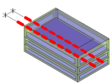
Average Vertical Void Height Threshold
This value is used to avoid the application of unwanted thermal loads and properties to analytical spaces like ceiling voids and small vertical spaces, such as closets and small storage spaces. When an analytical space's average height falls within this threshold, it will automatically be assigned to Unconditioned zone equipment. All analytical spaces assigned as Unconditioned are not included in any systems analyses. Analytical spaces do not have a height, so the Average Vertical Void Height Threshold is determined by dividing the volume by the area.
The default is 6 feet and is controlled by the Length unit in the Project Units dialog.
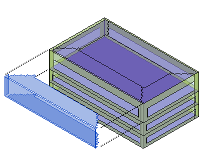
Horizontal Void/Chase Area Threshold
Similar to the Average Vertical Void Height Threshold, this value is used to avoid the application of unwanted thermal loads and properties to analytical spaces. When an analytical space's area falls within this threshold, it will also be assigned to Unconditioned zone equipment for exclusion from any systems analyses.
The default is 1 square foot and is controlled by the Length unit in the Project Units dialog.
Manage Thermal Properties
Revit offers three ways to specify material thermal properties of building elements for energy analysis. These methods can be used in combination with one another to suit different stages in the design process, levels of detail, and user preference.
- Conceptual Types are the default.
- Schematic Types, where enabled, override conceptual types.
- Use Detailed Elements, where enabled and where material thermal properties are specified for building elements, override both conceptual types and schematic types.
Conceptual Mass
This option is only available in the Conceptual Masses and Building Elements mode.
Mass Glazing
Specifies the percentage of exterior walls to be glazed openings (the window-to-wall ratio).
This setting applies only to conceptual masses with mass floors enabled.
Target Percentage Skylights
Specifies the percentage of roofs that should be skylights. This value is also known as the skylight-to-roof ratio (SRR).
This setting applies only to conceptual masses.
Advanced Setting
These settings are only available in Rooms or Spaces mode.
Export Complexity
- Simple - curtain walls and curtain systems are exported as a single opening (without individual panels). Simple is more appropriate for energy analysis.
- Simple with shading surfaces - same as simple, but with shading surface information exported.
- Complex - curtain walls and curtain systems are exported as multiple openings, panel by panel.
- Complex with shading surfaces - same as complex, but with shading surface information exported.
Shading surfaces are not associated with any room/space (roof overhang, free-standing wall).
- Complex with mullions and shading surfaces - same as complex, but with mullion and shading surface information exported.
Mullions in curtain walls are exported as shading surfaces. A simple analytical shading surface is produced from mullions, based on the centerline, thickness, and offset.
Sliver Space Tolerance
Specifies the tolerance for areas that will be considered sliver spaces.
Building Envelope
- Use Function Parameter. (default) This method uses the Function type parameter of walls and floors to determine the building elements considered to be part of the building envelope. If a wall has one adjacent space, analytical surfaces originating from the wall are classified as exterior surfaces. If a wall has two adjacent spaces and its function is Exterior, Foundation, Retaining, or Soffit, analytical surfaces originating from the wall are classified as interior surfaces. If the wall's function is Interior or Core Shaft, analytical surfaces originating from the wall are classified as interior surfaces, regardless of the number of adjacent spaces.
- Identify Exterior Elements. This method uses a combination of ray-casting and flood-fill algorithms to identify the building elements that are exposed to the outside of the building, the building envelope. Analytical surfaces originating from the building elements in the envelope are classified as exterior or shading surfaces.
Analytical Grid Cell Size
Specifies the cell size for the uniform cubical grid. This is the base size of the 3D grid cells, or cubes, used to divide the building shell bounding box into a uniform cubical 3D grid. This parameter is available when Building Envelope is set to Identify Exterior Elements.