By default, bars in a path shape distribution possess uniform dimensions. To allow bar dimensions to vary according to the specific concrete host, you can constrain either the bar segments, or the bar ends to the edges of the concrete element.
Constrain Segments to Edges
- Select the set and in Modify | Structural Rebar
 Constraints panel, click Edit Constraints.
- Select the segment handle.
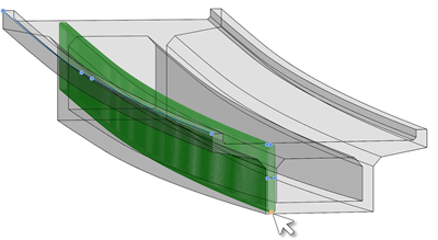
- Click a concrete element edge that it should follow. By default, the segment is constrained at cover.
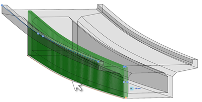
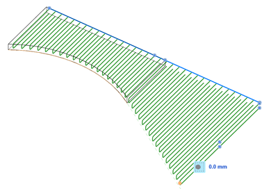
Bar ends have the same behavior. In the following example, constraining the bar end to the edge of the slab, extends the bars to that side.
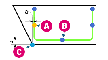
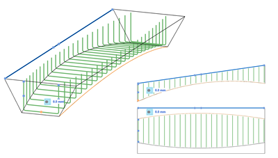
Note: The specified offset is applied for each bar in the set and is measured as the distance between the segment (line) or bar end to the selected edge (which is a point in each bar section). In the example below, segments (A) and (B) are constrained to edge (C) at offset a and b, respectively.
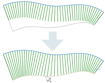
In the following example, segments 1 is constrained to the edge on the left, while segments 2 and 3 are both constrained to the edge on the right. All constraints are 0 mm offset to cover.
The edge constraint is extended on a tangent, when dragging the path end outside the host.
Note: You can select multiple continuous edges to ensure the correct variation of the rebar shape, if the concrete host is made up of several faces / edges.